Notice. New forum software under development. It's going to miss a few functions and look a bit ugly for a while, but I'm working on it full time now as the old forum was too unstable. Couple days, all good. If you notice any issues, please contact me.
phil99 Guru Joined: 11/02/2018 Location: AustraliaPosts: 3416
Posted: 08:19am 04 May 2026
Copy link to clipboard
Print this post
[32] Select Case click(ref) Error : REF is not declared
As you are using OPTION EXPLICIT it thinks REF is an undeclared variable. Have you set OPTION GUI CONTROLS xx ? Without that advanced controls won't work properly. It should appear in OPTION LIST.
See the first page of PicoMite Advanced Graphics manual. Edited 2026-05-04 18:19 by phil99
Bryan1 Guru Joined: 22/02/2006 Location: AustraliaPosts: 2297
Posted: 08:21am 04 May 2026
Copy link to clipboard
Print this post
Yep I'm on now reading that Advanced Graphics again and couldn't see the wood from the trees today,
Been reading up on the MsgBox() and I'm thinking as we can open a file this could open G-Code and by setting $values on the axis setup pages they could then be used for the stepper gc $'s.
I still have a long way to go getting it all the pages setup and it is nice to have a break from fabrication.
Edit: I was typing and missed your post Phill and yes I did set the GUI Controls to 75 before I started. Edited 2026-05-04 18:23 by Bryan1
matherp Guru Joined: 11/12/2012 Location: United KingdomPosts: 12052
Posted: 09:04am 04 May 2026
Copy link to clipboard
Print this post
Lyle Please could you test B5 to make sure I haven't broken anything. B5 now supports a 4th axis (A)
Bryan1 Guru Joined: 22/02/2006 Location: AustraliaPosts: 2297
Posted: 09:15am 04 May 2026
Copy link to clipboard
Print this post
Peter I'm running B4 and I may get enough dutch courage tomorrow with this gui and have a go at running the stepper. Now when I was using it yesterday I did notice a couple of times it kept going the error of no soft limits and only a reset stopped it. Now the code for the soft limits never changed in the code so not sure.
In the morning I can try it again and see if it happens again then take some screen shots.
mozzie Guru Joined: 15/06/2020 Location: AustraliaPosts: 469
Posted: 12:59pm 04 May 2026
Copy link to clipboard
Print this post
G'day Peter, Will load it up in the morning and report back, thanks for the additional A axis
I do wonder if you can read minds, I was planning a rotary engraving machine but was going to re-assign the Y-axis as the rotary. A call from my nephew with an idea for a project has moved it up the to-do list.
So many projects and only 2 hands...
Regards, Lyle.
PhenixRising Guru Joined: 07/11/2023 Location: United KingdomPosts: 2100
Posted: 07:22pm 04 May 2026
Copy link to clipboard
Print this post
Just a bit curious re: no A axis homing.
There are rotary tables with limited rotation and also, not every workpiece is circular.
Bryan1 Guru Joined: 22/02/2006 Location: AustraliaPosts: 2297
Posted: 02:35am 05 May 2026
Copy link to clipboard
Print this post
Ok next bit of fun Working off the Advanced Graphics Manual example got the radio button working but it just goes to a blank screen. now I have stripped back all the const's that weren't being used and made sure like the manual states the GUI button needs to be a higher #number and the new GUI area a lower # number.
I did change from the radio button to using the GUI LED
Now this code is a copy of whats in the manual and it still keeps going to a blank screen when either of the LED's are touched with the stylus
Sub TOUCHDOWN If Touch(ref) = 20 Then GUI page 2,5 'X1 #20 If Touch(ref) = 21 Then GUI page 3,5 'Y1 #21 If Touch(ref) = 22 Then GUI page 4,5 'Z1 #22 If Touch(ref) = 6 Then GUI page 1 End Sub
GUI PAGE 5 adds a button "MAIN" so you can get back to page 1
Now I'm off to bed...zzzzzzzz
Regards, Lyle. Edited 2026-05-06 03:17 by mozzie
Bryan1 Guru Joined: 22/02/2006 Location: AustraliaPosts: 2297
Posted: 06:35am 06 May 2026
Copy link to clipboard
Print this post
Many Thanks for finding that problem for me Lyle Well I'm now on 116 lines of code and as I used the const number where I had it all working I decided to change it over to each const name and still going thru all the error's that are popping up like where the #number worked now I'm getting this
[62] GUI caption Ycap,"Enter Y Length", 20, 125, RGB(green) '#37 Error : Expected a string
The code is now upto
Upload completed 1
Saved 4107 bytes > Time taken: 188362mS
So it taking around 3 minutes to load the code and I did find putting a extra comma got rid of the error
gui caption Ycap,"Enter Y Length", 20, 125,, rgb(green)
So getting there guy's and by the end of today when I get the code to work I will upload the code so you guy's can try it out
Still got code in the stepper interface and the way it is looking Peter's big board may be used as all the in/outs will exceed the 2350A chip.
So on each Axis page the global postion is shown and a number box is there for input, also on each page is toggle switch's which are needed so we can move each Axis into position before the job is started.
With page 5 that Lyle made I have the 6 led's needed for the limits and the E-Stop so it can be seen on each of the Axis pages and be a global page for each extra page made.
Now to get this code working I do think we need to get the toggle buttons on each axis working so we can setup movement on the steppers then we may just get over Version 0.001
Pretty soon I will get this code to work and it I think it has been a successful day getting this far.
Regards Bryan
Bryan1 Guru Joined: 22/02/2006 Location: AustraliaPosts: 2297
I do think it is time we cameup with a pin assignment so the stepper code can be inserted and Lyle hopefully you can have a play tonight with it.
Regards Bryan
Bryan1 Guru Joined: 22/02/2006 Location: AustraliaPosts: 2297
Posted: 08:08am 06 May 2026
Copy link to clipboard
Print this post
Well just had a look on my house computer for Sprint Layout only to find it kept hanging and couldn't find the download file.
So back onto Abacom via email and hopefully a new download file can be given so I can get on and design a PCB for this project which can be a universal PCB for the MMBasic Stepper Project.
Now thinking aloud about the pin assignments
As we are now upto 4 axis with 3 pins being enable, step and direction, 12 pin's.
6 pin's for the limit switch's, one for the E-Stop and one for the motor via a relay board.
Now for the E_Stop if it is Active Low a N/O external switch could be used so an external switch can be used for the E_Stop.
14 pin's if we use a SSD1934 LCD so we are now upto 34 pin's as I do think the ILI9488 3.5" LCD is too small to use as the interface so YES Peter's big 2350B board will be the best one to use.
To use the Brain Trust on this forum whats the biggest LCD screen we can use on SPI so the pin count can be reduced so a 2350A pico could be used.
Also I am thinking as a number box is on each axis the toggle component can be a multi component of that value.
Like with the Z axis where we have a grinding wheel doing 3500RPM each step is cut on the grinding wheel but the resolution still needs to be tested so now the code is ready to be advanced that will be my next task to get the Z axis going.
For the X axis I do have some 1/4" Chain sprockets, one is 56 teeth and the pinion is 15 teeth which is a 3.73:1 reduction so hopefully that will give enough torque for the rack and pinion X axis drive.
So tomorrow back on the tools and get all 3 axis hooked up so we can move forward.
Regards Bryan
Bryan1 Guru Joined: 22/02/2006 Location: AustraliaPosts: 2297
Posted: 08:42am 06 May 2026
Copy link to clipboard
Print this post
Cool Abacom just sent me a new download of Sprint Layout so got a new job tomorrow of designing the PCB.
Regards Bryan
Bryan1 Guru Joined: 22/02/2006 Location: AustraliaPosts: 2297
Posted: 11:16am 06 May 2026
Copy link to clipboard
Print this post
Ok with Peter's big 2350B board what is the side width of the pins on the board so I can make a start on the PCB as I am keen to get onto designing up this circuit board in Sprint Layout as I do feel that is the next thing to do as it will take time for JLCPCB to make and if they do parts on the board most parts can be SMD
I do feel a bit of Phenix is needed here so we take this PCB to another level
Regards Bryan
mozzie Guru Joined: 15/06/2020 Location: AustraliaPosts: 469
Posted: 01:12pm 06 May 2026
Copy link to clipboard
Print this post
G'day Bryan, Code is looking good
I measured the RP2350B board as 3.2" long x 1.1" wide.
Pins are 3.1" long (32 pins @ 0.1") and 1" pitch wide.
Going to be busy until Friday and then will have a play with your code and do some Stepper testing on V6.00.03 as well.
Regards, Lyle.
PhenixRising Guru Joined: 07/11/2023 Location: United KingdomPosts: 2100
Posted: 02:35pm 06 May 2026
Copy link to clipboard
Print this post
Oh heck. Mixtel90 is our resident SL6 guru
mozzie Guru Joined: 15/06/2020 Location: AustraliaPosts: 469
Posted: 12:24am 07 May 2026
Copy link to clipboard
Print this post
G'day, Just a thought, looking at display options would a 4" SPI LCD be a good compromise?
This would allow us to use a standard Pico2 module and have enough I/O for the stepper system as well. 4" seems to be the biggest display that is SPI interface off the shelf.
My eyes are slowly going as well but I tend to wear glasses while operating the machines anyway.
End of smoko, Back to work....
Regards, Lyle.
phil99 Guru Joined: 11/02/2018 Location: AustraliaPosts: 3416
Posted: 12:42am 07 May 2026
Copy link to clipboard
Print this post
Would connecting all Enable inputs to 1 Pico pin help?
Bryan1 Guru Joined: 22/02/2006 Location: AustraliaPosts: 2297
Posted: 01:04am 07 May 2026
Copy link to clipboard
Print this post
Morning Guy's well just ordered that 4" LCD and just got a message those pico 2 chips are ready to be picked up so let the fun begin.
mozzie Guru Joined: 15/06/2020 Location: AustraliaPosts: 469
Posted: 03:13am 07 May 2026
Copy link to clipboard
Print this post
G'day, Good thinking Phil, looking at Stepper.c it would appear the stepper enable pins are always activated / deactivated together so we simply enable one axis only:
if (stepper_drivers_enabled) { if (stepper_system.x.enable_pin != 0xFF) gpio_put(stepper_system.x.enable_pin, 1); if (stepper_system.y.enable_pin != 0xFF) gpio_put(stepper_system.y.enable_pin, 1); if (stepper_system.z.enable_pin != 0xFF) gpio_put(stepper_system.z.enable_pin, 1); stepper_drivers_enabled = false; }
That does assume I've read this correctly....
Bryan, I am thinking for testing purposes to use a PicoMite LCD Backpack PCB (from Silicon Chip) as I have a few spare, this gives us LCD connections / Touch and an SD card interface if needed. This has GP0-GP11,GP22,GP26-GP28 to use. If we go this way I can engrave the stepper system interface PCB's here and you can have one as well.
Also thinking of using a ULN2003 / ULN2803 for the interface to the stepper drivers but this is optional.
More testing to follow...
End of Lunch, Back to work....
Regards, Lyle.
Edit: GP8,GP9 are console if we use USB firmware for some reason, GP10,GP11 are used as I2C so best to use these 4 GPIO last I reckon. Edited 2026-05-07 13:23 by mozzie
Bryan1 Guru Joined: 22/02/2006 Location: AustraliaPosts: 2297
Posted: 03:55am 07 May 2026
Copy link to clipboard
Print this post
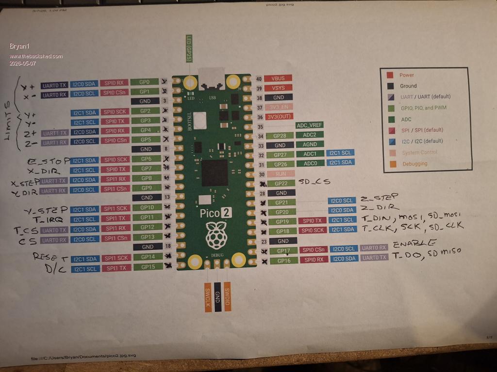
Hi Lyle I found a good picture of the pico 2 so just mapped out some pin assignments
This leaves GP26, GP27 and GP28 free so what do you think mate.
Now I am using my big breadboard for testing where I have 7 off push buttons to mimic the limits which did work a treat when I was using your sample code when I was testing the Y axis.
Got a big job to redo the breadboard and solder in the pins on the pico2 so that will take some time.
For the SPI LCD pinouts I got them straight from the pico manual
Regards Bryan Edited 2026-05-07 14:06 by Bryan1
Page 6 of 22
Print this page
The Back Shed's forum code is written, and hosted, in Australia.

 Notice. New forum software under development. It's going to miss a few functions and look a bit ugly for a while, but I'm working on it full time now as the old forum was too unstable. Couple days, all good. If you notice any issues, please contact me.


 Print this post


 Working off the Advanced Graphics Manual example got the radio button working but it just goes to a blank screen. now I have stripped back all the const's that weren't being used and made sure like the manual states the GUI button needs to be a higher #number and the new GUI area a lower # number.