
|
|
Forum Index : Windmills : The MPPT Project.
| Author | Message | ||||
| commanda Newbie Joined: 12/11/2007 Location: AustraliaPosts: 14 |
Hello everybody, I usually hang out on fieldlines, didn't realise there was a major thread on this subject here. I've been working on this on & off for several years now. I have a prototype analog mppt controller based on a 4046 pll. I'm also developing a universal dc-dc converter. Built in 2 halves. One half is the ferrite cored transformer, fets, gate driver, etc. Other half is the controller, and plugs into the first half with a connector. Controller can be configured to control input volts or output volts, and be powered from either the input or output. Also has an extra input for the output from the mppt controller. mppt description cut & paste from FL. A 4046 PLL is used as an oscillator to modulate the control voltage for the pwm. The 3 small op-amps give a signal derived from the generators output power. The first is a current amplifier, the second is an OTA analog multiplier (current times voltage = power), and the third is a differentiator. The 4046 includes a phase comparator. The 2 inputs to the phase comparator are the modulation signal and the power signal. The output of the phase comparator is integrated & becomes the dc control voltage for the pwm. There's also an input from the tacho, to quickly push the control voltage in the right direction as the wind changes. So, if the pwm modulation and the power feedback signal are in phase, we keep increasing the pwm control voltage. If they're out of phase, we decrease the pwm control voltage. Most of it still has much testing to be done, and still living in suburbia means it might be a fair while before it gets a proper run on a real windmill. Amanda |
||||
| Gizmo Admin Group Joined: 05/06/2004 Location: AustraliaPosts: 5182 |
Hi Amanda, welcome to the site. I've see a few of your threads on Fieldlines and I know TheBackShed will benefit from your input. Would you have any circuit diagrams or parts there of of your MPPT progress so far, I'm sure the other members would find it helpful with their own designs. Glen The best time to plant a tree was twenty years ago, the second best time is right now. JAQ |
||||
Megawatt Man Senior Member Joined: 03/05/2006 Location: AustraliaPosts: 119 |
Hello Amanda and as Gizmo has aaid, Welcome! There are a large number of people here who would be willing to make their rigs available to you for developmental purposes and some would even be close to you, wherever. Best Regards Megawatt Man |
||||
| commanda Newbie Joined: 12/11/2007 Location: AustraliaPosts: 14 |
For peer review and comment. I also have a Protel dos pcb layout if anybody wants to build one. 2007-11-14_120905_09590140.pdf.zip Amanda |
||||
| GWatPE Senior Member Joined: 01/09/2006 Location: AustraliaPosts: 2127 |
Hi commanda, Is the DOS version EASYTRAX. I still use EASYTRAX for all of my designs. Luckily I still have a postscript printer and the application still runs under WinXP. Not bad for a program that I bought in 1989. I will look at your schematic in detail, but at this stage I only notice the use of some high value resistors. You need good conformal coatings for reliability. cheers, Gordon. become more energy aware |
||||
herbnz Senior Member Joined: 18/02/2007 Location: New ZealandPosts: 258 |
Hi I am still trying to come up with a smps design. In my reading I have come across capacitor only versions usually step up such as voltage doublers etc that john has mentioned but there is also discussion about using them as voltage reducers and requlators .Often refered to as capacitor pumps very little info i can find on their use as smps other than brief mentions of high eff possible. Any one know why they not popular ? I still see a lot of effort going into this posting on the control if we can come up with a switching convertor controlled by a DC control I believe we will then be better placed to experiment with control. Get the horse in front of the cart. Amanda Can we see details of your power switching cct ? Herb |
||||
| commanda Newbie Joined: 12/11/2007 Location: AustraliaPosts: 14 |
Herb, Capacitor based designs are generally only good for low power applications. If you study how computer power supplies work you'll be most of the way there. My current guinea pig is a simplified pc power supply circuit, using fets as the switching elements with dc drive, and not isolating the input and output sides. There is someone I know (online) who has figured out how to modify a pc power supply to get a fully voltage adjustable, current limit adjustable power supply. It's then only a matter of fitting a series resistor between the TL494 voltage ref pin and the op-amp input pin, and another series resistor from there to the outside world; then you can modulate the voltage control with an external voltage. So if you set the default output voltage to equal a dead flat battery, and use the external control voltage to increase the output voltage, with the minimal line resistance from power supply to battery, you've got it. Gordon, My Protel version is Autotrax, which I believe is file compatible with easytrax. Amanda |
||||
| GWatPE Senior Member Joined: 01/09/2006 Location: AustraliaPosts: 2127 |
Thanks Amanda, Yes it is. I have downloaded autotrax and I will stick to easytrax. Programs are similar, but graphics drivers not correct for my laptop. Autorouting places tracks in dumb places. Biological computer does a better job. I have also looked at expressSCH and expressPCB. I have been side tracked from the MPPT of late. I have just finished the control cct for my gridfeed inverters. Excess power from wind and solar now gets to be used in the AC connected appliances, or used by others on the grid. The system is now like a hybrid UPS with battery draw only if there is no sun and no wind, or no grid. Battery stays at float most of the day. The only time power may be wasted as systems shut down is when the grid is down. No where for the surplus power to go, so individual solar and wind regulation ccts cut in. The stand alone inverter still powers appliances connected to it as one micro detects mains failure and deactivates a changeover relay to switch the inverter bypass OFF when the grid fails. I am still prototyping the data exchange between micros. I will use this control method so I can use N-channel mosfets for high side switching in the Buck/Boost MPPT. There will be similar PWM code in 2 modulators. The power and MPPT calculation data from one micro will be coupled to either the Buck PWM micro or Boost PWM micro. The opto coupled data transfer method will keep DC isolation for high side switching and enable a more linear response and eliminate the dead end problem with most analogue modulators. A tested prototype is still a way off yet. cheers, Gordon. become more energy aware |
||||
| Megawatt Man Senior Member Joined: 03/05/2006 Location: AustraliaPosts: 119 |
Well done so far GWatPE. I too am interested in the field of grid connected inverters, but being an electrical power engineer learning new electronic stuff I feel a little constrained. If you were to search for my posts you'd see that I have concerns about fast transients and their destructive effect, particularly on SMPSs. Now I note that zero crossing detectors have inherent delays in them unless there's predictive timing circuit to ensure exact coincidence between a dead zero and a switching operation and so a fast transient can be expected every half cycle. Snubbing is used for small currents, but can we effectively snub say 8 amps? What all this leads to is what technique have you used to reduce switching transients? Gizmo, although this is related, you may prefer a different thread? Megawatt Man |
||||
| GWatPE Senior Member Joined: 01/09/2006 Location: AustraliaPosts: 2127 |
Hi Megawatt Man, Snubbing is about reducing high speed transients. High peak voltages for a short duration. Having a low impedance for the energy to be redirected is the key. All of my switching ccts employ full spectrum bypassing up to 100MHz on the input. [ie lots of different value caps in parallel, pF to 0.02F with at least 1 value per decade] There should be square edges on the swithing device when the voltage is viewed with a CRO. The flyback from a transformer I snub with a high speed diode into a low impedance cap and then bleed the power back to the supply rail. Buck and boost ccts already have the inductor ends snubbbed with a cap on one end and the diode feeding a cap on the other. I use a screened PCB design. I hope this answers your questions. I leave the grid connect AC to the PRO's. Too hard to get approval certification to go alone. I only work on the DC side. All of the AC mains fixed wiring stuff has been installed by my sparky mate. I used to design and build DC-240VAC inverters and 415VAC solar water pumping systems. My interests have now moved to control and high efficiency designs. My hybrid home system gives me opportunity to test what I design. cheers, Gordon. become more energy aware |
||||
| davef Guru Joined: 14/05/2006 Location: New ZealandPosts: 499 |
"All of my switching ccts employ full spectrum bypassing up to 100MHz on the input. [ie lots of different value caps in parallel, pF to 0.02F with at least 1 value per decade]." I would suggest doing a circuit analysis on multiple capacitors in parallel with their associated inductance values. The more different values caps in parallel the more frequencies that they do not bypass. You might be unlucky and not bypass an important frequency. A free circuit simulator like RFSim99 is easy to operate and tells you where you might have problems. The usual cure for this problem are small value resistors in series with specific caps to reduce the effect of unwanted resonances in the bypass system. These can only be found by circuit simulation. Regards, |
||||
| GWatPE Senior Member Joined: 01/09/2006 Location: AustraliaPosts: 2127 |
Hi Dave, I see you have an engineering background. I have looked at the simulator you posted. I do not have an L meter. You cannot simulate unless you can specify components values. If you look at many of the ccts posted you will notice a lack of adequate high frequency power supply bypassing. I think you will find most readers are looking for help with issues and would have some difficulty programming a simulator program. It would be helpful if you were to provide some examples as well. Many a Circuit design exhibits poor performance because layout of the final design introduces undesirable effects. A simulator may predict something will be OK, but when we backshedders come to build it, well you can can guess an outcome. There is an issue with SMPS and the like is that poor design and building can result in undesirable RFI. The production of efficient switching and modulation creates other technical problems that need to be adressed as well. These problems are one reason I am reluctant to offer cct designs for general use. I use an iterative process using a CRO to determine the best component values that achieve desired results. My rule of thumb is if a component does not get hot while performing the desired function and the CRO trace shows a sharp switching waveform and my TV and radio don't suffer then the cct is working well. Other readers may offer some experience they have had with snubbing real switching ccts. cheers, Gordon. become more energy aware |
||||
| davef Guru Joined: 14/05/2006 Location: New ZealandPosts: 499 |
Gordon, Correct, you either need to measure the inductance of the capacitors you are using or get someone to do that for you. Chip caps these days usually have that information in the datasheet, but you are more likely to be using leaded components. Also, how these caps are physically wired will have a huge impact on the resultant spurious parallel resonant behaviour. The other way to gain insight would be to do a frequency sweep of your bypass system using a spectrum analyser with a tracking generator. Perhaps, a friend in radio comms is needed! Here is one RFSim99 example below. You will see the series resonant notch of the 100nF cap with 10nH internal inductance to be 5.0MHz and the a similar notch for the 10nF and 10nH part to be 16.0 MHz. The key point to notice is the parallel resonant frequency of 11.8 MHz, here you have NO bypassing. Some maths will show that the 10nF/10nH cap is resonanting with the internal inductance of the 100nF cap. The trick is to put a small resistor, in this case about 0.5 Ohms in series with the larger cap to reduce the "parallel resonant peak" to a much lower level. Of course, making this resistor too large reduces the effectiveness of the bypassing afforded by the 100nF cap. Also, 10nH is possibly a bit low. From memory typical polycarbonate caps, as used in most switch mode supplies are more like 20nH. And, as a "rule of thumb" each 1mm of connecting wire adds another 1nH to the equation. PCB trace inductance can be estimated published data or measured as well. You appear to have developed other techniques for working around the problem. I found out how to format a screenshot using PAINT on the help page but can not figure out how to attach a .jpg to this mail. Could you tell me how? Regards, davef |
||||
| GWatPE Senior Member Joined: 01/09/2006 Location: AustraliaPosts: 2127 |
Hi Dave, Your info confirms my findings about the value of the series inductance. I have pretty well sussed the RFSimm program. I calculated the approximate series inductance with the ceramic chip capacitors that connect to the groundplane. The program calculates the 1.6mm pinning wire out at <1nH. I use large pads at the filter end of the inductor and the chip caps bridge the gap to the heavy screen track that is pinned to the groundplane on the other side of the board. The only caps that have leads are PCB electro's of 10,000uF and 1,000uF. I estimated the series inductance of these to be <2nH. When I have my boards done, the ground plane will be pinned every 5mm with plated through holes, to connect the ground between both sides where they overlap, [basically no extra cost], so the resistance to ground will be very low with the resultant very low parasitic inductance. The ground plane effectively places a parallel capacitance to ground for every printed circuit track as well. Too hard to calculate all the interactive effects. Remember there is a huge series inductor with caps effectively on both ends. The cct employs a complex low pass Besel filter on the output. Here is something like the cct. I scanned from 1kHz to 1GHz with only a tiny low pass at 1kHz. Basically only DC comes out. I used 0.1ohm, the minimum for the input and output Z 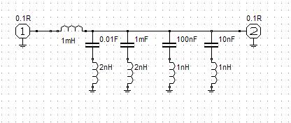
The input filter is similar. It helps to have a very low effective series inductance with the caps. Other designers on thebackshed may not use the same techniques as me, so their ccts would behave differently. I hope Megawatt Man has enough info on snubbers now, or is more confused. cheers, Gordon. become more energy aware |
||||
| GWatPE Senior Member Joined: 01/09/2006 Location: AustraliaPosts: 2127 |
Hi all, I have found that transferring digital data between 2 picaxe chips interferes with the control function that is critical to the task to be achieved. I have scrapped this and have designed another approach that uses the picaxe to digitize the measurement. The signal is a linear representation still, but digital. This signal can be linearly opto coupled to other pic chips and read as a normal analogue input. The pic chips act as interfaces still and perform dedicated functions. The MPPT has to respond to mill voltage and current and battery voltage to produce a PWM output. The AXE-08M cannot do this alone. The pwm signal has to be calculated. This signal has to be routed to either the buck or boost cct. The buck cct has a different ground reference to the boost cct. The function to boost or buck is determined by comparing the generator voltage with the output voltage on the battery, which changes with the state of charge. The battery earth is not common to the generator, and the positive isn't either. I have devised a way or converting the measured battery voltage and digitally transferring this to the circuitry referenced to the generator earth. This digital signal is then linearly converted to analogue and compared with the analogue generator voltage. The logical output controls which modulator is used. Each of the Pic function blocks can be in circuit reprogrammed and logged without affecting the operation of the MPPT. Only simple resistor dividers are needed in the measurements. I have chosen to use an Allegro Hall effect current sensor that can be placed in series, anywhere in the DC generator wiring. This is attached with a fly lead. The battery voltage measuring cct is connected with a fly lead as well. Each of these components is electrically isolated from the mill cct. The cct board will end up being about 100mm x 75mm. The logging function would be done by a separate micro that captures data from each module, collates it and the dumps to EEprom or a PC. Remember that the MPPT will allow your mill to produce more power at the bottom and top end. I will look at the option of parallel operation to increase power transfer. Sorry but this will only be suitable for 24V systems at the moment as I am using 55V Mosfets. cheers, Gordon. become more energy aware |
||||
| davef Guru Joined: 14/05/2006 Location: New ZealandPosts: 499 |
Gordon, Remove the 1mH inductor and look at the 4 capacitor combination with 0.1 Ohms on input and output. No bypassing at 84kHz. Now the ESR of the caps will reduce that "peak", so you are seeing a worst case scenario. If the noise is generated at the input (before the 1mH inductor), looking after the inductor will show very low or no noise. But if the noise source is at the output end AND happens to be at 84 kHz it won't be bypassed to ground. Now, maybe this is not important in your situation. How did you attach the RFSim99 image? Cheers, davef |
||||
| GWatPE Senior Member Joined: 01/09/2006 Location: AustraliaPosts: 2127 |
Hi davef, I have thought about your comments a little more and I can see where you are coming from. I think my bypassing reigime can be streamlined with a simpler cct. I will add a larger main cap, 30000uF for the main carrier reduction and a trial and error on the prototype for the edge switching harmonic. It is alwayws a tradeoff between switching speed and component sizing. I will assume you are using a PC running Win98, WinXP. To captur a screen shot, use Alt & PrtSc. This will copy the current screen contents to the clipboard. Just paste into paint. Cut the section of the screen of interest. Open a new paintsession without saving changes, then paste the previous cut. Then just save the file in a JPEG format. This file will be small enough to post on a forum by using the 2nd most right button on the post reply window [image upload]. I hope this helps. cheers, Gordon. become more energy aware |
||||
| davef Guru Joined: 14/05/2006 Location: New ZealandPosts: 499 |
Gordon, Thanks for the clue in the last line. I had looked at each of those buttons and was confused by the verbose pop-up message. When I saw . . . javascript:openWin etc, I seized up!! |
||||
| GWatPE Senior Member Joined: 01/09/2006 Location: AustraliaPosts: 2127 |
No worries davef, I just get IMAGE UPLOAD when I move over that button. You must be using IExplorer 7 maybe. Hi all, MPPT is now on track, with some possible useful spinoff ccts. I am now looking at an RF link for data transfer. Would be useful to measure variables on the mill head or a long distance away. cheers, Gordon. become more energy aware |
||||
| domwild Guru Joined: 16/12/2005 Location: AustraliaPosts: 873 |
Gordon, As the answer(hope) to your concerns: 1. Why not use a larger Picaxe, like the 28 or 40? Then there would be enough storage, etc. for more code. 2. A larger Picaxe would also no longer require interfacing between modules as larger Picaxe's have more I/O pins. Regards, Taxation as a means of achieving prosperity is like a man standing inside a bucket trying to lift himself up. Winston Churchill |
||||
| The Back Shed's forum code is written, and hosted, in Australia. | © JAQ Software 2026 |
