
|
|
Forum Index : Electronics : Mab1's wiseguy inverter build - transformer options
| Author | Message | ||||
| KeepIS Guru Joined: 13/10/2014 Location: AustraliaPosts: 2177 |
If everything else is wired correctly then changing the 5V reg to wiseguys modified 5V circuit as you have done should stop that flashing  The only effect of a higher value Precharge resistor is a slower startup time before the capacitor banks are charged equal to the Battery voltage, then the Nano enables the Solenoid and SPWM. _ Edited 2025-07-15 14:01 by KeepIS NANO:Inverter V 8.2ks - Linux AvrDude GUI script V4.1 |
||||
| mab1 Senior Member Joined: 10/02/2015 Location: United KingdomPosts: 282 |
It already has wiseguys 5v regulator, but I think the cycling was to do with the economiser: when it was cycling on and off there were clunks coming from the solenoid. But it now has the keepis arrangement and just displays inv off and the dropping cap voltage until the cap bank has discharged So the inverter box is finished (the transformer lives outside the box, and the post transformer bits will too for now). I've added an extra turn to the primary of the (temporary) transformer, 27 turns, approx 27v. With 26 turns I was getting 76% pwm at min battery volts*, and 62% pwm at max battery volts. But there's no room for another turn even if I need it. *I've ended up with a slightly non standard battery voltage: battery 1 is 15s liion, and battery 2 will be 17s lifepo4, so it's sort of 50v rather than 48v. 15s made more efficient use of the available ev battery modules than 14s |
||||
| KeepIS Guru Joined: 13/10/2014 Location: AustraliaPosts: 2177 |
Sounds like everything is running as it should  My 16S LiFePO4 banks sit between 52.4V (loaded) after running overnight and 54V (charging) as I only charge to around 92% to 96% depending on tail time by the end of the day. Really great to see the journey from the start of the build to a fully running Inverter. _ Edited 2025-07-16 16:00 by KeepIS NANO:Inverter V 8.2ks - Linux AvrDude GUI script V4.1 |
||||
| wiseguy Guru Joined: 21/06/2018 Location: AustraliaPosts: 1296 |
I moved my comments & description of inverter on/off back to Wiseguys New Inverter Build Nano Rev6 Here Now it doesn't clog MAB1's thread and is probably better placed. Edited 2025-07-18 10:39 by wiseguy If at first you dont succeed, I suggest you avoid sky diving.... Cheers Mike |
||||
| KeepIS Guru Joined: 13/10/2014 Location: AustraliaPosts: 2177 |
Thanks for the insight, although I would not call this a "stuff up", especially in light of the enormous amount of work involved for you at the time, bringing this rapidly changing and evolving project together resulting in such a powerful elegant robust design for a truly superb DIY Inverter, including the brilliant code design and programming skills from Poida for his Core Nano SPWM driver. NANO:Inverter V 8.2ks - Linux AvrDude GUI script V4.1 |
||||
disco4now Guru Joined: 18/12/2014 Location: AustraliaPosts: 1127 |
Will the forward voltage drop on the diode in the circuit for pre-charging the capacitors mean they won't quite get to VBat and need an adjustment in the setup to account for it? F4 H7FotSF4xGT |
||||
| wiseguy Guru Joined: 21/06/2018 Location: AustraliaPosts: 1296 |
Good question, in Poidas code we put a known voltage simultaneously on the Vcap and Vbat inputs and calibrate them both simultaneously to the known Vbat voltage. That way resistor tolerances are taken into account and calibrated for. There would be an offset error that the diode causes to the Vcap that becomes more prominent the closer we get to zero volts. I'm going to ask KeepIS what the prognosis is for the added diode, and when calibrating should it be with the diode included for better accuracy at the region of interest, or does version two need more work.... or more lipstick... Circuits in question: 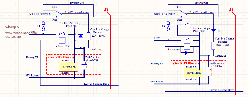 Edited 2025-07-18 11:46 by wiseguy If at first you dont succeed, I suggest you avoid sky diving.... Cheers Mike |
||||
| KeepIS Guru Joined: 13/10/2014 Location: AustraliaPosts: 2177 |
The diode should not cause any issue and if used should be installed when calibrating, VBat to VCap delta is only relevant when the Inverter is above low voltage cutout and SPWM / Solenoid are enabled. My code also has a more stringent delta test immediately after Solenoid enable (and a different code), IMHO in either case, the calibration of VCap with a Diode in series should only have an influence at very low voltages when the Solenoid is switched off, as wiseguy indicated, that difference should be meaningless to the code at low V. EDIT: Just to be clear, there are separate calibration settings for Vbat and VCap in my Code, and allowable Delta is adjustable up to 3V if needed. _ Edited 2025-07-18 15:44 by KeepIS NANO:Inverter V 8.2ks - Linux AvrDude GUI script V4.1 |
||||
| mab1 Senior Member Joined: 10/02/2015 Location: United KingdomPosts: 282 |
Probably not your stuff up but mine Wiseguy  I downloaded copies of the schematics early on so I wouldn't have to go looking for them when I needed them. But I didn't check to see if it was the latest version when I came to use it I downloaded copies of the schematics early on so I wouldn't have to go looking for them when I needed them. But I didn't check to see if it was the latest version when I came to use it  Finally got it connected to the battery today: 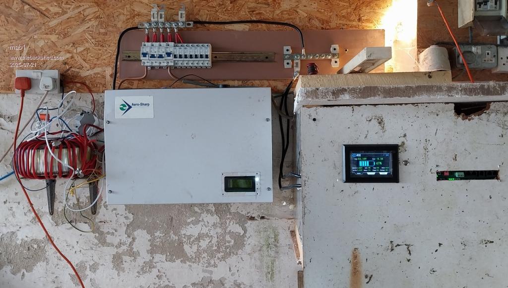 Not yet tidied up on the ac side but ok to start testing. Tried a couple of small loads then connected the mahoosive chest freezer as a longer term test, and to see how it was with a big start surge - fine, although it did manage to trip once in about 5hrs on overcurrent. I don't have any solar connected to the 48v battery yet, so once i was sure it was happy with the freezer I switched a couple of gti solar arrays onto it as they're on plugs and easy to transfer over. I can't recall if anyone else was planning to backfeed with gtis, and it wasn't very sunny so it was only 500w, but the inverter didn't bat an eye when backfeeding Gradually left it for longer periods but kept popping back to check as I don't want the freezer to defrost, but then after about 5hrs from Startup, I came back to this: 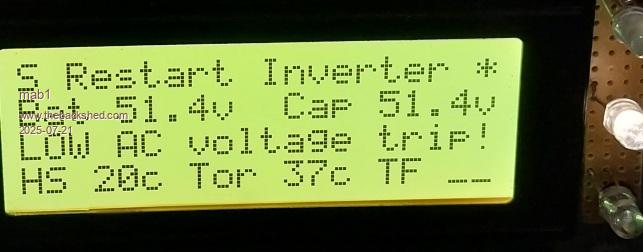 Note the torroid temp was high. I couldn't really figure out what had happened so I reset the inverter- it started fine and started the freezer fine, but the transformer seemed a bit noisy, and after a couple of minutes it was getting louder and rougher sounding, and seemed to be pulling a couple more d.c. amps than it ought, so I unplugged the freezer. The transformer got quieter, but was still loud, and was getting louder even with no load, and putting my hand on it, the primary was getting hot  so I turned the inverter off. so I turned the inverter off.Thinking about it, I'm guessing I'm losing drive to one corner of the h-bridge (again  - i had that on the test bench, but i fixed that solder joint for sure)? But I'm not sure yet and need to do some testing - i had that on the test bench, but i fixed that solder joint for sure)? But I'm not sure yet and need to do some testing  . I'm guessing I must have a dodgy solder joint somewhere. . I'm guessing I must have a dodgy solder joint somewhere.Edited 2025-07-21 10:32 by mab1 |
||||
| wiseguy Guru Joined: 21/06/2018 Location: AustraliaPosts: 1296 |
I'm glad the smoke has not been let out so far. Highly recommend that you get a scope on the output to see the waveform shape. Did you use quality machined IC sockets? - I tried some cheapies from AliExpress and it caused many hours of chasing intermittent faults. Some of the machined pin sockets had zero tension with a pin inserted - gravity would make it disconnect when testing each pin of each socket. The ones that had some tension were only about 1/4 to 1/2 of a good quality socket. What value choke/s are you using in total? I found for a 48V inverter ~ 47uH was about the right starting number. I calculated for my 2KW 12V inverter as ~ 5uH but made the mistake of starting with that value unloaded. It turned out ~12uH was the right value - are you seeing a pattern here? A few have asked for a "rule of thumb" guide to the choke value. I suggest that a good starting point seems to be ~1uH for each volt and expect only ~ 30 - 50% of that starting value remaining under load & depending on the core material. I will do more work on this eventually. If at first you dont succeed, I suggest you avoid sky diving.... Cheers Mike |
||||
| KeepIS Guru Joined: 13/10/2014 Location: AustraliaPosts: 2177 |
Might be best to go back to a current limited supply with a small value of Cap bank just in case, you should notice any extra current fairly quickly with that, and an intermittent board fault shouldn't blow the FETs. Interestingly heatsink temps look fine. I noticed it has turned on the Toroid fan enable, 37°C is not really that hot though but it may have been a lot hotter before the trip? NANO:Inverter V 8.2ks - Linux AvrDude GUI script V4.1 |
||||
| mab1 Senior Member Joined: 10/02/2015 Location: United KingdomPosts: 282 |
 yes I was impressed that it didn't let the magic smoke out, but I'll still use a bench psu and small caps when I try and trace the fault - no use tempting fate. yes I was impressed that it didn't let the magic smoke out, but I'll still use a bench psu and small caps when I try and trace the fault - no use tempting fate.I remembered your warning about cheap Chinese sockets so I avoided ali - but I think I may have gotten them from lcsc who are, technically, Chinese now There are two chokes, about 25uH each, 5 turns on 5 blue sendust(probably) rings, and according to my attempt to measure their saturation, should be OK up to the high side of 400A. And 5.4uF (1 + 2 x 2.2) capacitance on the transformer output, plus 10nF to 0v from each side of the primary as per your schematic. Keepis, yes I was surprised there was no heat discernable in the heatsink/caps if there was enough current to heat the 16mm2 primary in a couple of mins , particularly as the battery current was <10A. I guess it was in core saturation spikes from the cap bank?I don't actually have any fans set up yet so i haven't looked at the settings: in theory I'm not pushing it past the 3kw transformer rating yet, so it should cool passively. The chest freezer can pull 400w when it's working hard, but more usually 250 - 300w. |
||||
| KeepIS Guru Joined: 13/10/2014 Location: AustraliaPosts: 2177 |
The power rating of the Toroid is limited by the the power handling of the two windings, not by the size of the Core, with good cooling a given Core can be pushed to very high power levels, 16mm2 input would definitely limit continuous power rating. You might want to check the two 2.2uF caps just in case one is leaking, maybe try a value around 3.3uF as well just to rule out a problem there. Skin effect is at play in the Chokes, terminals and winding of the Toroid, any connection or cable quality issues in that area will make the cable appear smaller in cross sectional area from a heating and current handling perspective. Good luck NANO:Inverter V 8.2ks - Linux AvrDude GUI script V4.1 |
||||
| wiseguy Guru Joined: 21/06/2018 Location: AustraliaPosts: 1296 |
I think mab1 is on the right track with regard to unequal drive. It would be easy to saturate the core in one direction with the slightest difference in the two halves of the sine wave pwm drive. That is the main reason why there is audible noise coupled with heating of the toroid primary, despite little to no secondary load delivery. Edited 2025-07-22 11:14 by wiseguy If at first you dont succeed, I suggest you avoid sky diving.... Cheers Mike |
||||
| mab1 Senior Member Joined: 10/02/2015 Location: United KingdomPosts: 282 |
Ok, haven't been able to look at the inverter til today due to work  But got home earlier today and not too tired so I fired it up on a 2A bench psu and 2000uF capacitance, and looking at the waveforms on the little pocket'scope:- running fine with no issues, even when prodding/poking/wiggling things in their sockets. 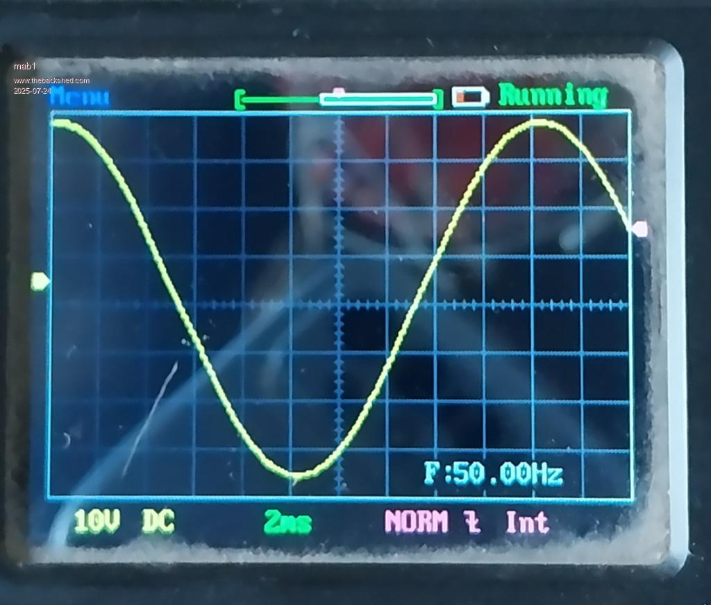 Sinewave (via the weller iron 24v transformer) looks ok to me. Left it running with a small led lamp and a Weller 40w soldering iron for a load (with a small cap and 2A fast limiter on the psu, that's about all it can do). After about an hour I heard the kilovac clunk (I'd bypassed it with the bench psu, but it was easier to leave it under nano control): the fault had returned . The inverter was cycling: ramp up, then audible erratic 'ticks' from the tranny, then the amps ramping up to 2, voltage drops so 5v shuts down, then volts recover so inverter reboots. There did indeed seem to be asymmetric drive, but I was struggling to determine which quarter of the H-drive it was using the scope. In the end I resorted to prodding things to see if it would change, and OC1 and/or OC3 did indeed change the speed of the inverter cycling, so I shut it down and pulled them. They're smd on the little boards WG supplied so i suspect my soldering . No-one's ventured an opinion on lcsc ic sockets so I'm assuming they're OK.I resoldered the optos and reinserted them, and then re-did the other two for good measure. The inverter has been going (still on bench psu and small cap) for about 4 hours now so keeping my fingers crossed  . It doesn't react to prods and wiggles to the optos.... yet. . It doesn't react to prods and wiggles to the optos.... yet.Still using the 5.2uF caps as I didn't want to change too much at once, although I do wonder how the value of 5uF has been determined. Does it relate to inductor value or pwm frequency or just empirically determined as about right? I do recall warpspeed advocating for tuning to 75Hz but that was not followed here, but I can't remember where 5uF came from Edited 2025-07-24 07:44 by mab1 |
||||
| wiseguy Guru Joined: 21/06/2018 Location: AustraliaPosts: 1296 |
To test the ic sockets use the leg of a new 1N4148/1N914 etc diode which should have nice noticeable gentle tension against inserting/removal on each pin socket. Another hint, when assembling the "plug in" opto module I use an IC socket to hold the pin strips, now perfectly aligned before soldering the other end to the little pcb adaptor. Hopefully the resoldering did the trick. Edited 2025-07-24 10:10 by wiseguy If at first you dont succeed, I suggest you avoid sky diving.... Cheers Mike |
||||
| mab1 Senior Member Joined: 10/02/2015 Location: United KingdomPosts: 282 |
Thanks . I've tried your socket test on a random selection of holes on the part-assembled variac board (same ic sockets) and they seem to have a respectable hold to me I suspected my soldering as I remember doing the optos when I was tired, but doing it anyway cos i was getting frustrated with my lack of progress  more haste, less speed! more haste, less speed!Anyway, it seems fine: after about 8hrs on the bench psu I transferred it to the battery via a 6A breaker, then later to a 20A breaker with the freezer and gti, then today on the 80A breaker, two gti's, and the freezer and a couple of other bits, and it seems happy back feeding 40+ amps into the battery |
||||
| mab1 Senior Member Joined: 10/02/2015 Location: United KingdomPosts: 282 |
The temporary transformer is the aerosharp with all it's existing windings, primary and secondary intact, so 16mm is the biggest I can fit. I was thinking 16mm would suffice for 3kva, but since your comments I've noticed the primary getting warmer than i was expecting - and realised there was a flaw in my thinking: I was thinking 3kva @battery voltage (50 - 60v) would equate to about 60A, which 16mm should handle; but of course it's not battery voltage, it's the 26 or 27v for 230v out that the primary it wound for, and 3kva @27 volts is a lot more amps. So for testing to higher loads I've cobbled up another temporary transformer: 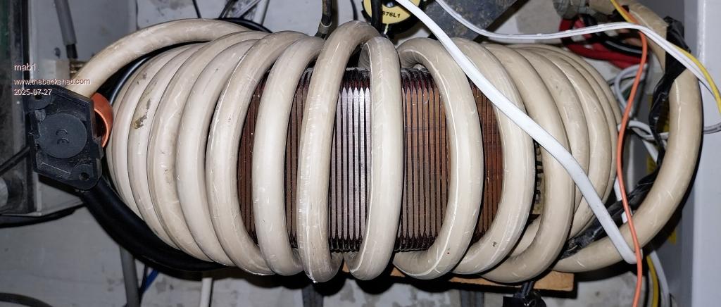 This is the variac core with 37 turns of 50mm2 . Using the 230v winding as it is so runs about 16W at 230v Due to the smaller core cross section it needs more turns/volt, but there's room for 70mm2 in that huge centre hole (50 is what I've got). Although my inductors are still wound with 16mm2 for now I ought to get on with winding the double stack really, but I feel it may be worth playing a bit with transformers first. |
||||
| KeepIS Guru Joined: 13/10/2014 Location: AustraliaPosts: 2177 |
I use 35mm2 for the chokes, they run at the same temps as the 52mm2 Toroid windings at the continuous power levels I run with this Inverter, I would not wind chokes with heaver 52mm2 cable even if it would fit, I've given my reasons before but that's just my opinion for keeping the FETS alive if the sh#t hits the fan. I feel for you with the Toroid dilemma, it's the hardest part of the build in most cases IMHO, I was fortunate in being able to find 6 identical specific Toroids from old GTI Inverters for my build. On the plus side, it's knowing that any effort put in is richly rewarded with this great Inverter design. NANO:Inverter V 8.2ks - Linux AvrDude GUI script V4.1 |
||||
| mab1 Senior Member Joined: 10/02/2015 Location: United KingdomPosts: 282 |
Yes, I'll have to get some 35mm2 for the chokes at some point, but my 16mm2 chokes may be keeping my fets safe for now. The toroid winding is my own fault I could've part unwound them as suggested by you and/or Wiseguy but I decided to unwind them completely . Still, it'll feel like the right choice once it's actually wound - I hope Update: having resoldered the optos, it was running much nicer, but there still seemed to be noticeable transformer noise when running under load, but oddly, got quieter when backfed from the gti's, even at higher power. It made me wonder if I still had asymmetric drive - the gti's are sunny boy transformer types so they would obviously push back with a symmetrical output. Had the idea of measuring the primary current using the clamp meter set to d.c. and sure enough, it was consistently showing 1 amp or more in one direction even with no load connected. 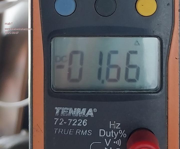 With 2kw load it would nudge up towards 3A. When backfeeding it was too noisy to be sure, but given that other people's builds have quiet transformers, it was time to go back to the test bench.  Thinking it could be another dodgy solder joint , I tried to think of a way to test the whole gate drive, optos, and totem pole drivers: decided to use a signal generator to drive a 10khz 5v-0v square wave into each opto in turn and look at the mosfet gate signal in each case: Actually turned out easier to spot than that: for 3 of the optos, applying the 10khz signal caused the 12v supply currect to increase from 55mA to around 78mA for the high side drives, and about 86mA for one of the low side drives, and I could actually hear the 10khz drive faintly. For the 4th opto (one that had had a bad solder joint) there was no increase from 55mA and no noise! Soldered a new opto in and bingo! All four drives work and produce a square wave on the gate resistors (although, there was still a slight difference in the current draw for the two lowside drives: about 86mA for one and 94mA for the newly installed one - I'm still thinking about that ).So reassembled the inverter with a transformer and: 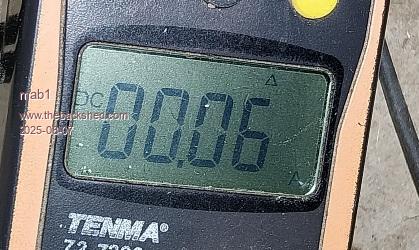  almost inaudible! almost inaudible!It's been running running quietly ever since - except:- every now and then the transformer does make a little noise, and using the clampmeter, it does coincide with a small dc current (0.3 - 0.5A). It seems to build smoothly over a few seconds, then fades gradually over several minutes, then it will be quiet with no measurable d.c. for the best part of an hour before doing it again - I can't figure what could cause it and it dies it irrespective of if there's any load connected or not. I tried wiggling the optos, just in case it was a dodgy socket, but even moving them about in their sockets has no effect. Tried one of the other programmed nanos, but it's not that either. I don't know if that's small enough imbalance to not worry about or not. Edited 2025-08-07 09:51 by mab1 |
||||
| The Back Shed's forum code is written, and hosted, in Australia. | © JAQ Software 2026 |
