
|
|
Forum Index : Microcontroller and PC projects : PicoMite Alpha Firmware
| Author | Message | ||||
| CaptainBoing Guru Joined: 07/09/2016 Location: United KingdomPosts: 2171 |
Thanks for this. So it is morning now and I have a bit more time to play. It seems to be just one of the three. I tested everything directly into a USB port on my laptop and got the same thing. Took the other two, plugged them in with no other action and all started flashing away as they should. It seems I have a partially failed Pico... I have marked it accordingly so it doesn't get used in anger and it looks like I can still use it for dev on my desk. At 3.60GBP, hardly worth contacting the supplier (Pimoroni) as I don't know that it was DOA. a bit surprised at that. Perhaps we are seeing a faulty batch. One day I will track it down, only two components involved. Forgot to add... in all my "flashings", I had a prog stored in slot 10 and it survived everything. So I erased all the flash and power cycled the thing - no difference, which tends to vindicate the flash chip and point to a problem with the RP2040 bootstrap. Edited 2021-06-04 17:15 by CaptainBoing |
||||
| Mixtel90 Guru Joined: 05/10/2019 Location: United KingdomPosts: 8983 |
It also rules out any of the F4 programs that use bigger screens - which (apparently) can't be SPI because of speed issues. Beginners probably don't have experience of the other MMBasic systems (or they wouldn't be beginners :) )so whether they have to designate pins is a moot point. They'll also be working from the manual rather from memories of other systems. We don't know what's going to happen yet, which is why I said "probably". At the moment we have FLASH CHAIN which isn't supported by anything else. *If* the PIO state machines get implemented that's going to be a deal breaker. The Pico is also a dual-core processor which *might* open up other options in future. It's certainly more capable in some ways than the other MMBasic platforms. The Pico isn't a super MM+ and won't be without the advanced graphics. That's one of the key areas where the F4 is the closest. The flexibility with pin layout can't be underestimated, especially as the Pico can easily be soldered directly to a pcb for embedding. It could easily make the difference between having to use commercial double-sided boards and home made single-sided. You can get loads of tracks away from it on a SS board. Even if pin allocation was compulsory it would still be very easy to write transportable programs in many cases. The only problem comes with making *existing* programs transportable, and that always requires work anyway. Adding a few PIN allocations at the beginning is nothing compared to correcting graphics. Almost all programs are written for and on a particular system and even the authors say "It should run ok on ... but it's not been tested". . Edited 2021-06-04 18:03 by Mixtel90 Mick Zilog Inside! nascom.info for Nascom & Gemini Preliminary MMBasic docs & my PCB designs |
||||
| CaptainBoing Guru Joined: 07/09/2016 Location: United KingdomPosts: 2171 |
yeah it is. It will be used as an embedded controller in place of 170 Mk2s etc. many times more than as a "poor man's" CMM2, despite the language enhancements. I am already re-designing three projects to take it, one of which can have dozens of 28pin 170s as slaves (soon to be PPMs) per installation, with hundreds installed total. Not going to be swapping them out wholesale but if the PiPicoMite ends up where I hope, the new modules will be fitted in place of the old in repair/extend/new installations - I am instantly saving around a fiver per slave which I can pass on to be more competitive. I have also shelved my plan to buy more 170s in the next couple of months. on the pin assignments... If there are a set of defaults beforehand and the new argument for SETPIN is optional, everybody happy  @MatherP: language request - are there enough command slots to allow a SWAP statement for variables?  easy enough to do in Basic but sloooowww easy enough to do in Basic but sloooowwwEdited 2021-06-04 22:12 by CaptainBoing |
||||
| lizby Guru Joined: 17/05/2016 Location: United StatesPosts: 3833 |
I hope Peter will support 480*320 3.5 inch SPI serial LCD modules ILI9486 ILI9488 ILI9481. Some programs using 4.3" 480x272 SSD1963 LCDs might run without change on the PicoMite (though not using the bottom part of the screen). The programs which I wrote to use 4.3", 7", and 9" SSD1963 screens all scaled the display based on mm.hres and mm.vres, so they would probably work on a 3.5" SPI LCD, though they might need tweeking. Of course, the PicoMite won't support the large LCDs themselves. Hardware PIO state machines would certainly be an enhancement to MMBasic, but likely to be a niche use. Nothing about having default (but changeable) pin assignments should inhibit this. I'm not sure how that follows. To my mind, a "super MM+" is a module which runs MMBasic which supports SD, runs faster than the MM+, and costs $4. Nothing about "pre-allocated but changeable" would make this unobtainable. "Adding a few PIN allocations at the beginning is nothing compared to correcting graphics." I'm hoping to see LCD support (with BLIT) before too long, and we can see just how much correcting is required. Correcting is more likely to have to do with mm.hres and mm.vres than with, for instance, SPI vs parallel LCD except when speed is an absolute requirement (and then we might be talking CMM2 anyway). PicoMite, Armmite F4, SensorKits, MMBasic Hardware, Games, etc. on FOTS |
||||
| Mixtel90 Guru Joined: 05/10/2019 Location: United KingdomPosts: 8983 |
Defaults aren't always good, IMHO. ;) Because of hard-wired defaults, the MM Backpack only has 8 usable IO in total, one of those is shared between analogue in and PWM out - you can't have both. (The rest are 5v tolerant). I know that's not a fair comparison, but I think it highlights my point about defaults being restrictive. The Pico has 26 IO pins. Now set some as defaults: 2 for a UART 2 for a I2C 4 for display SPI 1 for touch CS 4 for SD card That's 13 gone - half the IO pins, 3 of what's left are also analogue inputs. I'd consider that to be pretty restrictive. I know you could disable the ports you aren't using to get the pins back, but why not just allocate what you need? You'll rarely need all that lot configuring anyway. No defaults have been set for Count, PWM or for second UART, I2C or SPI ports. Edited 2021-06-04 22:46 by Mixtel90 Mick Zilog Inside! nascom.info for Nascom & Gemini Preliminary MMBasic docs & my PCB designs |
||||
| CaptainBoing Guru Joined: 07/09/2016 Location: United KingdomPosts: 2171 |
I see where you are coming from - sorry, I was not clear... On a standard Mk2, you can use the UART/SPI/I2C pins as IO. If you do and then try to open the associated interface you get an error. It should be the same with the PPM - all pins can be IO with special functions only if you call/make allowance for them. when I said defaults, I did not mean "dedicated". I meant that UART1 is on pins a & b, I2C1 is on pins m and n but just as the other mites, those pins can still be declared as bog standard IO if you want. So you see, you haven't lost any IO capability. If all you need is IO, you got it. I have rarely (struggling to think of *any*) designed anything that uses every peripheral but, yes, I'd be boiled if I had pins available but "sterilized" when I needed them. Incidentally, this ties in to my earlier question about the "hard" CS pin for the SPI ports. Don't like that a lot. Easy enough to get round but sterilizes that pin. SPI CS should always be under program control. As for the 5V tolerance, that's a nice to have but any design work has to consider the maxes and mins, otherwise why can't I plug a Mk2 into the 12V on my car? The designer has to be aware of limitations, and new-comers will learn the lesson quickly (as I have many times). A friend who is completely illiterate to this (in his defence it's not his line of work) destroyed a TomTom GPS by cutting off the cigarette lighter part of the cable and permanently mounting the thing in his car - beautiful cable management - and dead GPS... at a time when they were still north of 200 quid! It wasn't 12V tolerant. Edited 2021-06-04 23:40 by CaptainBoing |
||||
| Mixtel90 Guru Joined: 05/10/2019 Location: United KingdomPosts: 8983 |
How will you know what the defaults are, I wonder? Adding the PIN command makes it clear, but omitting it tells you nothing. I know... RTFM! :) Mick Zilog Inside! nascom.info for Nascom & Gemini Preliminary MMBasic docs & my PCB designs |
||||
| CaptainBoing Guru Joined: 07/09/2016 Location: United KingdomPosts: 2171 |
erm... I was kind of hoping for some documentation along the lines of... 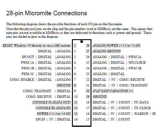 ... which clearly shows what comes out where, in the case of the PPM it would show the defaults... without making any language changes mandatory. If you wanna change them around, knock yourself out, but out of the box this is where they are. That's got to help new-comers rather than forcing them to understand the mapping fabric. That could come later - it's quite advanced for "Hello World". I reckon the majority of these would see their entire working lives in default mapping - I know I wouldn't be changing it unless I had a problem routing tracks or similar. this is the same for everything, you must learn what to connect to where, even the manual for my toaster tells me where to put the bread. I am struggling to see why this is a biggie. . Edited 2021-06-05 00:11 by CaptainBoing |
||||
| thwill Guru Joined: 16/09/2019 Location: United KingdomPosts: 4380 |
If my vote counts for anything and given I am a micro-controller newcomer I can only agree with the Captain. Best wishes, Tom MMBasic for Linux, Game*Mite, CMM2 Welcome Tape, Creaky old text adventures |
||||
| Mixtel90 Guru Joined: 05/10/2019 Location: United KingdomPosts: 8983 |
I seem to have been outvoted... I shall, therefore, retire gracefully and accept default allocations. :) @matherp I assume the PIN commands wouldn't be mandatory for the defaults? I see you propose I2C0 on pins 6/7. As it's not possible to get I2C1 on the other side without losing 2 ADC pins or SP0, how about making pins 26/27 the I2C0 default? That would allow several alternatives for I2C1 on the other side and still get access to I2C1 on the same side if one of those sacrifices can be made. It would also allow 2x8-bit or 1x16-bit parallel ports on one side if UART0 isn't used. Mick Zilog Inside! nascom.info for Nascom & Gemini Preliminary MMBasic docs & my PCB designs |
||||
| matherp Guru Joined: 11/12/2012 Location: United KingdomPosts: 11673 |
That is exactly what I posted earlier 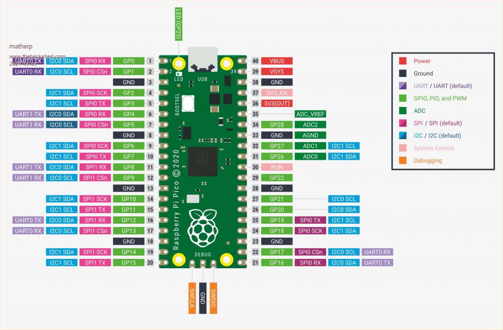 This is the diagram that everyone using a Pico will see. If I lock UART0 to pins 0 and 1 then the "official" diagram makes no sense and people will immediately ask for them on another pairing. Likewise even allocating a default seems wrong. If I default to pins 0 and 1 but someone wants 21 and 22 then they need to undo the default first. The beauty of SETPIN is that anyone used to MMBasic understands that this is used to configure a pin for a purpose DOUT, DIN, AIN, PER etc. In some ways MMBasic is illogical that the same doesn't apply to UARTS and SPI but that is largely because of the inflexibility of the original H/W (the PIC32 Maximite chip has no flexibility in pin assignment of these functions) I take on board your various comments but I'm going to side with Mixtel90 - no defaults and use of SETPIN to allocate a function to any pin that can support it e.g. SETPIN UART0 21,22 SETPIN SPI1 14,15,16 Note setting up SPI does not AFAIK lock up the CSn pin. CS will be controlled from MMBasic allowing multiple SPI devices on the same bus. The only deviation from this will be the LCD pins and the SDcard pins. At the moment I'm bitbanging the SDcard pins (same as the CMM2). Experience on the CMM2 has shown that it is much easier to get reliable SDcard access doing this than with H/W SPI and at no performance penalty. In the case of the LCD and SDcard on the Pico. I intend that these will be flexibly allocated via an OPTION command |
||||
| robert.rozee Guru Joined: 31/12/2012 Location: New ZealandPosts: 2542 |
given that the pins used for each function are reconfigurable, it makes sense to me to NOT have a default allocation. you might save the odd line of source using a default, but when reading someone else's code, or a long program, it will require a line-by-line search to ensure that a default is being used. a bit like checking if there are any tigers in africa, it is easy to miss a single line of code and end up making a wrong assumption about what pins a function uses. the MM mk2 et al are always going to be different in this regard because the design of the chip FIXES what pins are used for each function. we need to embrace the similarities, but also recognize the differences that require incompatible syntax. also, we are encouraged to explicitly declare variables, so why should pin allocations be any different? just my opinion, mind you. some folks seem to have remarkably strong views on this matter! cheers, rob :-) addendum: snap! peter was writing at the same time as me! Edited 2021-06-05 03:21 by robert.rozee |
||||
| Mixtel90 Guru Joined: 05/10/2019 Location: United KingdomPosts: 8983 |
I might not retire quite so gracefully after all then. :) Defining pins makes sense to someone coming from MicroPython: led_onboard = machine.Pin(25, machine.Pin.OUT) led_onboard.value(1) becomes CONST led_onboard = gp25 setpin led_onboard, dout pin(led_onboard) = 1 and import machine sda=machine.Pin(0) scl=machine.Pin(1) i2c=machine.I2C(0,sda=sda, scl=scl, freq=400000) Edited 2021-06-05 04:05 by Mixtel90 Mick Zilog Inside! nascom.info for Nascom & Gemini Preliminary MMBasic docs & my PCB designs |
||||
| lizby Guru Joined: 17/05/2016 Location: United StatesPosts: 3833 |
Does this imply that the LCD is also bit-banged? Will the LCD and the SD card share the same pins, or may they be different? (Just curiosity, I have no notion regarding any benefit in making them different.) PicoMite, Armmite F4, SensorKits, MMBasic Hardware, Games, etc. on FOTS |
||||
| matherp Guru Joined: 11/12/2012 Location: United KingdomPosts: 11673 |
TBD  Just run the very simple speedtest on the PicoMite and am getting just under 76000 lines per second. Edited 2021-06-05 05:21 by matherp |
||||
| CaptainBoing Guru Joined: 07/09/2016 Location: United KingdomPosts: 2171 |
That pic is not same thing as it shows multiple instances for each peripheral, with the micromite diagram there is no uncertainty. Newbies are going to look at that and faint. In the introduction, have a modified version of that diagram showing default positions and then in the advanced programming section that pic above showing all the alternate positions for peripherals and how to remap to them. Surely applying a default config in the firmware can't be that hard to do in the name of compatibility? Then we are able to simply drop into opening up the I2C peripheral from the word go just like all the other 'mite platforms? I know nothing is impossible for the person not doing the work, but I fail to see why this gets in the way of anything and the plus is immediate access and easy understanding. ... with no defaults, code immediately become non-portable without a PiPicoMite specific setup in MMBasic. it breaks compatibility. You expect to define IO pins but now we need to run chunks of code only if the platform is one thing or another - expect to see stuff like this in any program where portability is needed - unique and mandatory to the Pico. Select Case MM.Device$ Case "RP2040 PicoMite" SETPIN UART0 p,q SETPIN UART1 x,y SETPIN SPI1 d,e,f SETPIN SPI2 a,b,c SETPIN I2C1 k,l,m SETPIN I2C2 a,b,c End Select which is not necessary if we have firmware startup defaults. And if the pins are perceived as fixed by many, what harm is done? For me the strength of MMBasic is portability between platforms... I guess not so much for others. . |
||||
| CaptainBoing Guru Joined: 07/09/2016 Location: United KingdomPosts: 2171 |
so every bit of code you run on the Pico needs editing first (beyond the IO settings). Madness. I think the opposite will be true. If defaults are given, people will use it as it comes out of the box, you'll only get thrown a curve ball when you have to venture into someones idea of how it should be done rather than every time. And I bet most will leave the peripherals where they are. Semantics - the Pico is functionally a direct (evolved) replacement to the Mk2, far from being different it is effectively an upgraded version of the same thing - a small embedded controller - proof? look at all the emphasis on the IO and peripherals. Compare to the CMM2 (which is the only platform *substantially* different) - predominantly a games machine - who has written traditional micro-controller-territory stuff for the CMM2? I bet not many. I am not saying use fixed pins, I am saying have a set of defaults applied when the firmware boots so you can use the peripherals without configuring first - having to do so will confuse and alienate people who don't understand this stuff. Beyond vast amounts of existing code that now won't directly run on the Pico. . Edited 2021-06-05 07:52 by CaptainBoing |
||||
| matherp Guru Joined: 11/12/2012 Location: United KingdomPosts: 11673 |
Sorry - decision made. All variants need changes as pin numbers are different between platforms - try setpin 1,dout on each |
||||
TassyJim Guru Joined: 07/08/2011 Location: AustraliaPosts: 6550 |
Just about every program I write has (or should have) something along the lines of DIM INTEGER dht_pin = 27 to allow users to tune the program to their hardware. Having SETPIN SPI1 d,e,f SETPIN SPI2 a,b,c added to the setup is no different. If you produce some hardware, you will tell the users which pins do what... Jim VK7JH MMedit |
||||
| Mixtel90 Guru Joined: 05/10/2019 Location: United KingdomPosts: 8983 |
I've always liked to name IO using CONST at the beginning. It makes life so much easier swapping pins round when I'm trying to fit a PIC on a pcb. :) It's almost a habit now. Honestly, I really can't see how configuring IO pins would put people off. Completely new programmers will be following the manual and examples, so it's no problem to them. Those who have programmed in C/C++ or Python have already got used to doing it - and had to include libraries to get access to the pins in the first place. It only affects existing MMBasic programmers, many of whom have already used more than one platform and are aware that there are differences in how they work. Anyone who has only programmed on a C64 will be lost, of course, because that hardly counts as BASIC. ;) As for software compatibility, expecting to pick up a piece of code written on a F4, drop it on a CMM2 and expect it to run perfectly isn't going to work unless it's something very simple. It doesn't work with a Pico program dropped on a MX170 either. Almost everything needs *some* conversion. There's probably already a block of SETPINs that need to be changed so adding a few more shouldn't be much of a hassle. Unless you are trying to fit your prog into the last byte of memory, of course. Mick Zilog Inside! nascom.info for Nascom & Gemini Preliminary MMBasic docs & my PCB designs |
||||
| The Back Shed's forum code is written, and hosted, in Australia. | © JAQ Software 2026 |
