
|
|
Forum Index : Electronics : Bryan's Inverter build
| Author | Message | ||||
Bryan1 Guru Joined: 22/02/2006 Location: AustraliaPosts: 2100 |
Well while I was grinding some 1.5mm gal plate for the back cover heard a bang and found some black plastic close to my foot, couldn't see what it was so just kept going and the sparks were no near the battery either. 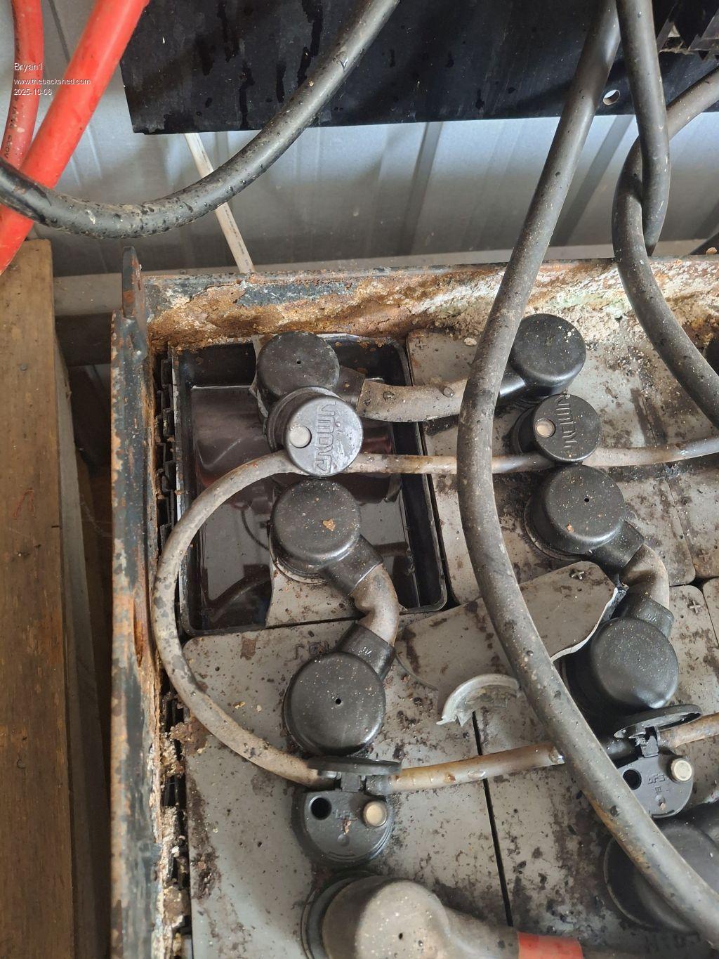 Just did a voltage check and the battery is still holding voltage so that is a good sign  Now there is another battery where the lid is raised and I can't really complain as I did get this battery free back in 2012 Now there is another battery where the lid is raised and I can't really complain as I did get this battery free back in 2012 Now I do think with this build some Ceil 1000AH cells may be needed to replace this battery. I will stay on 24 volts too as can't see the justification of spending all that money just to go on 48 volts. Edited 2025-10-06 13:47 by Bryan1 |
||||
| rogerdw Guru Joined: 22/10/2019 Location: AustraliaPosts: 955 |
That's a bit nasty Bryan and I'm glad they didn't all go off. I'm in a facebook group of forklift battery users and one of the guys had his blow up ... and he successfully stuck them all back together again using hot glue. Some were cracked down the sides and glue even sealed them too. Also a reminder for me to not be too casual around mine. I keep a fan running over them while they are charging but I also need to be aware of not creating sparks with charging leads etc.  Cheers, Roger |
||||
| Bryan1 Guru Joined: 22/02/2006 Location: AustraliaPosts: 2100 |
Well good news on my shed battery as that cell that blew it's lid is still good and the batteries are fully charged for the weekend Cut some 6mm perspex today at work for clamping ontop of the heatsinks and in the morning I go to the 12 volt shop and get more cable and a 175 amp anderson connector so a bit more work can be done. Cleaned up the box last weekend and gave the inside a coat of white paint to clean the box up. Pic's will come later this weekend Regards Bryan |
||||
| Bryan1 Guru Joined: 22/02/2006 Location: AustraliaPosts: 2100 |
Well had a look at Ali tracking and it still said 7 days on the weekend before they get off their butt and sending the package  Just checked now and it says 2 days before shipping. Just checked now and it says 2 days before shipping.Anyway installed a din rail and got onto ebay and bought a energy meter the same as Rogers so for the AC output I will put in some circuit breakers along with that energy meter so got a visual of whats going on.As the brain board still needed the nano soldered in got it all setup tonight and hoping if all goes well tomorrow got 60+ soldering joints to do, ain't soldered circuit boards in ages so time to get back in the swing I think. Now for the main driver board I did find some old brackets to fit the job so by using the outer holes on the circuit board will allow the the battery connections to pass under between the gap and just need to bend up some plate to mount them.Now I did buy a 450 amp DC isolator ages ago so I'm thinking as inverter box is so close to the batteries of getting a second one so both the DC wires can go via the on/off switch's doing away with the Anderson connector idea. Now as Keepis did say when those toroids finally did ship they were at his door before he knew it so time to get moving on this project.Regards Bryan |
||||
| Bryan1 Guru Joined: 22/02/2006 Location: AustraliaPosts: 2100 |
Well just checked ali and and my toroids have finally shipped also got that energy meter today so got question for Roger did you setup the wifi for this energy meter as the destruction's do give a guide on how to set it up.Also bent up the supports for the main board at work today and talked the boss at work to let me work tomorrow as the time line is getting shorter before the next audit so it does look like I may be working a 6 day week may be on for the next month or longer. So I have lost the window to get the thick cable this weekend so I can get it on the way home from work on Monday. I do have a good picture in my head how this is going to be setup but before any power is turned on plenty of pic's and a keen eye from the experts will be needed as I will also be hooking up this Goodwe 5kw gridtie as those 6 off 190 watt panels according to my victron 100/50 isn't getting the shed battery to float but on checking the SG tells a different story where the SG meter is sitting in the green. I do have a second voltage controller relay and can liberate the 35 amp relay from the house project that has stalled as the 1.9Kw array has the batteries on float around lunch time. Now on saying this watch the season change and the 2.4Kw split system on the house will be needed so my wife can stay cool thru the day so that SunnyBoy Gridtie project will be needed to be completed for the house array. Regards Bryan |
||||
| Godoh Guru Joined: 26/09/2020 Location: AustraliaPosts: 667 |
Hi Bryan, just wondering if you have the Victron controller set to the right battery type. I have some 50 amp victron controllers in my system , from memory they have a rotary switch to set the battery type. If the controller is set to the wrong battery type then that may explain why it thinks they are ready for floating. Pete |
||||
| Bryan1 Guru Joined: 22/02/2006 Location: AustraliaPosts: 2100 |
Pete with my Victron MPPT's they are all bluetooth controlled and I have set the voltage to 29.2 for float and looking at history the battery voltage just never got there. now I have left the shed going so my beers stay cool  and with close to 4Kw input the batteries are getting to 28.88 volts but the SG does tell a different story. and with close to 4Kw input the batteries are getting to 28.88 volts but the SG does tell a different story.when I got these batteries back in '12 my mate did say 1024 SG was the fully charged point, now on looking today they are sitting close to 1030 and looking at that battery that lost it's top not my bubbles are being produced. anyway I am working tomorrow so when I do get to my shed I may see a different story as the MTTP may well be in float and the current off the shed is enough to keep the voltage down |
||||
| mab1 Senior Member Joined: 10/02/2015 Location: United KingdomPosts: 282 |
29.2v seems a bit high for float to me:- I'd be setting 27.6 for float, 28.4 to 28.8 for absorb, and 29.2 for equalisation. Unless it's very cold where you are, I'd guess you must get through a lot of deionised water. |
||||
| Bryan1 Guru Joined: 22/02/2006 Location: AustraliaPosts: 2100 |
Ok I made a mistake on the Victron voltage as it is set for 29 volts and with the grid tie connected thats the trip point I can set the voltage controlled rely at. I'm now on planning the layout and writing up a journal of tasks to do so I have a good guide to getting this done. Now with the LM35 I did notice yonks ago it was externally mounted on a huge heatsink and I did find in my stuff a old computer main chip heatsink with 12 fan attached. Now for mounting that heatsink some 2mm plate can go thru a fin then get bolted to the side of the box. Now it would be nice to monitor the temp of this on the LCD so a question for Poida are there any spare pins on the nano where a a 10K thermister can be hooked up |
||||
| Bryan1 Guru Joined: 22/02/2006 Location: AustraliaPosts: 2100 |
Well I am starting to wonder if Ali has got me for $165 for those sundust rings Now gotta ask just to buy these online from Element7 or one of the others just so I can have a date for delivery then when/if these toroids turn up they will be needed for the second inverter build as after the first build I'm sure lessons will be learned. Working a 6 day week here so when I do get all the parts to finish I do think another mind will be needed so Roger just soldering on the connections needs a bigger soldering iron I own so I'm sure you will have on bigger enough that we could use Regards Bryan Edited 2025-10-24 17:48 by Bryan1 |
||||
| Bryan1 Guru Joined: 22/02/2006 Location: AustraliaPosts: 2100 |
Well this Ali order has finally shipped and I'm getting emails everytime there is an update so I just hope I do get these toroids and not another handle like my last order.So I do reckon they should be here early next week so yes time to get restarted on this project and a stop at the 12 volt shop will happen to get the thick wire. |
||||
| Bryan1 Guru Joined: 22/02/2006 Location: AustraliaPosts: 2100 |
Had a bit of time this afternoon so got the perspex top done with drilling and tapping 2 off M3 threads on each sink so the heatsinks are all aligned. Now as it been suggested using both pads on VS1 and VS2 which will a tight fit for wire so just squashed some 1/2" copper tube and ended up with 18x3 mm so I could make a bussbar and put 2 of those M4 connectors on each pad then bring it out for the external connection to thick wire. Now just cut some 3/8 and 1/2 copper up where the 3/8 copper just slid in, heated the copper up to bright red to anneal it then gave a few smashes with my 4lb hammer where I got 18x4.5mm Also the battery connection under the board can be the same where a copper bussbar is made. Now for the PCB stand off's got 12 of them to make so that box of M3x12 SHS will come in handy for securing everything. |
||||
| Godoh Guru Joined: 26/09/2020 Location: AustraliaPosts: 667 |
Hi Bryan, I have done the same in the past, used copper pipe to make lugs, and busbars. It is handy to have a few offcuts in the shed. Bits of heatshrink on the flattened tube work well as insulation. Good luck with the build Pete |
||||
| Bryan1 Guru Joined: 22/02/2006 Location: AustraliaPosts: 2100 |
G'Day Guy's, Well finally got confirmation from Aussie post this shipment off the slow boat will be here in the morning or the next day I annealed 2 0ff 400mm hard drawn copper and found a second anneal was needed to get the pipe flat and straight. I have more than enough to do both sides of the board now with VS1 and VS2 the bussbar just needs to clear the board by some so with using 2 of those 4mm mounts for each pad a total of 16 was needed. I still need to get the M3 spacers so a trip after work on Friday I call into Jaycar and grab them so I can set the base plates for the main power board. Got some 6mm perspex for mounting the brain board. So slowly getting there and a busy weekend is on the cards. Regards Bryan |
||||
| Bryan1 Guru Joined: 22/02/2006 Location: AustraliaPosts: 2100 |
Got an email stating this package had finally arrived so picked it up after work along with my new Tee shirt from ARSE 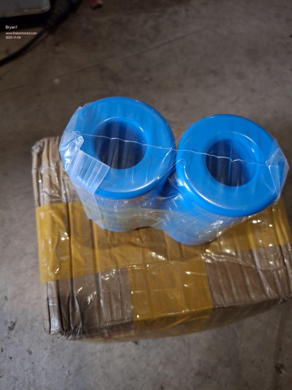 So I do think a stop tomorrow after work to the 12 volt shop to buy a few metres of 35sqmm so winding the toroids can be the job Saturday after work Now a question for those that have done these chokes is it best to glue the toroids together to make one long toroid which I do think will make winding it easier. Also with those 400mm long 18x3 copper strips I am thinking of adding some 6.5X4 wire I have here and with a good anneal I can get it nice and straight then just soft solder them onto the 18x3 as I do think beefing them up with more copper will make a decent bussbar. Edited 2025-11-06 17:17 by Bryan1 |
||||
Revlac Guru Joined: 31/12/2016 Location: AustraliaPosts: 1277 |
They look good, no damage either. Fun making copper buss bars, I looked at some nice thick copper bar available at some local shop, nope not getting any of it at those prices, I still have enough, but in future if we want a fancy buss bar it might be worth melting down some scrap copper and casting our own, finish it off in the milling machine.  Your build is going well. Cheers Aaron Off The Grid |
||||
| KeepIS Guru Joined: 13/10/2014 Location: AustraliaPosts: 2177 |
Great to see they arrived, could you tell me what the code is on the side of the toroid rings? Thanks. NANO:Inverter V 8.2ks - Linux AvrDude GUI script V4.1 |
||||
| Bryan1 Guru Joined: 22/02/2006 Location: AustraliaPosts: 2100 |
Well finally finished work for the week and I stopped into Jaycar to get the M3x15mm tapped spacers and missed the cut for the 12 volt shop. Anyway the code: MM571060A 21MB1G1 So my aim is to get the main board mounted so it can go on the table and my old Kipoint can under on the shelf. As theres no way the big toroid is going in the case until the case is mounted as it will be heavy to lift. Well got the main board mounted and I'm using all 8 holes in the PCB so the pcb can sit nice and flat in operation. 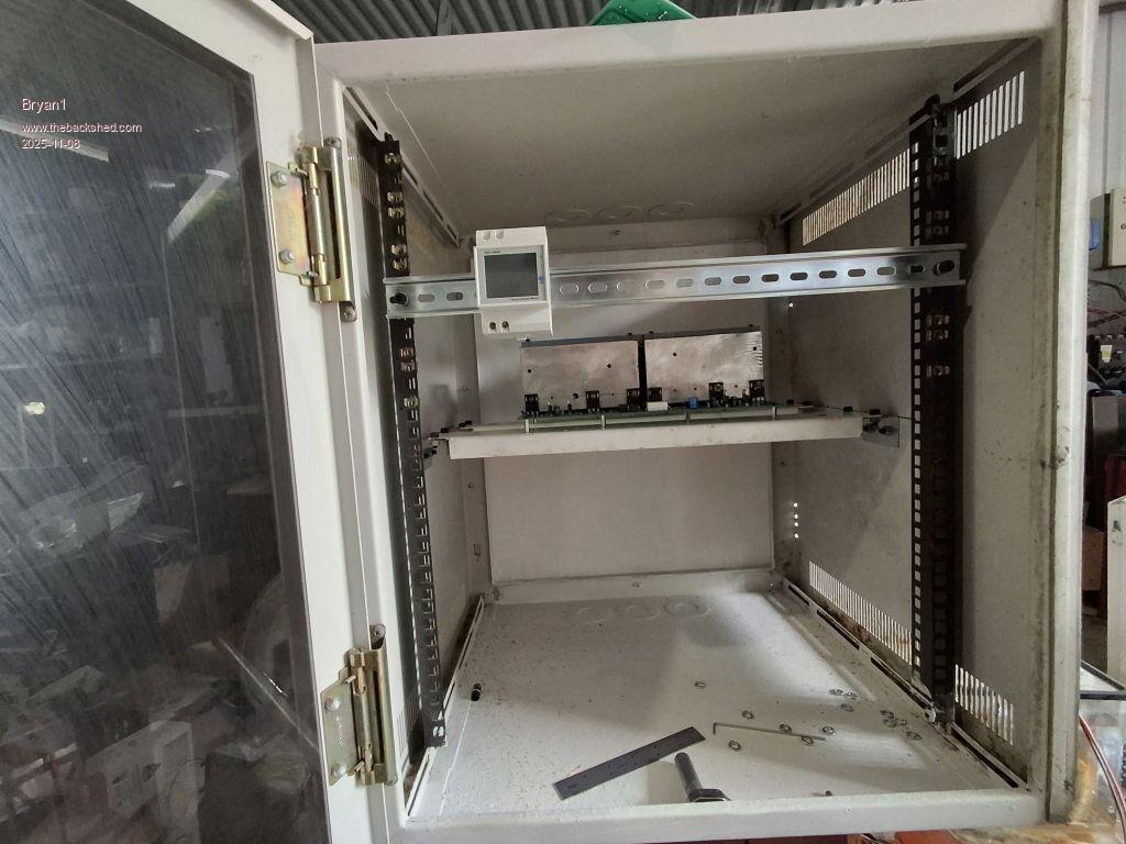 The toroid and chokes will sit on the base so the wiring will be nice and close, still got the bussbars to finish and it does look like a Sunday morning with a coffee will a good time to get back working with copper. Now for the brain board I do have a 240x100mm perspex 6mm thick and it will be mounted on the righthand side so it can hold the brainboard and the buck converter. That 2mm bit of plate I cut worked out well for holding the heatsink for the TIP35 which can go off the left wall. I am also thinking that 175 amp anderson connector is a good idea as I'm going to put that 450 amp switch on the negative and a very short cable to the switch as it will be mounted on my main DC power board. Edited 2025-11-08 16:19 by Bryan1 |
||||
| Bryan1 Guru Joined: 22/02/2006 Location: AustraliaPosts: 2100 |
Last weekend I went over to Roger's and he soldered up the Nano and the nano to the board for me was record time while looking at some of the solder pads I did a close look did show the old IC sockets were tarnished and the solder didn't flow properly. Now I am going to have a close look at the main board and check all the soldering I did just to make sure everything is right.Talking with the sparkie at work today and the talk was on for finding some 35sqmm wire and soon found close to a full roll then he found 4 off 8mm lugs and did say they had the crimper there so going to 100mm for one end and 350mm for the other end which goes to the main board.So the question was asked to my boss so tomorrow I'm taking the toroids and my inductance meter then thats another major task out of the way. |
||||
| Bryan1 Guru Joined: 22/02/2006 Location: AustraliaPosts: 2100 |
Well we did find some time at work and had the first try and soon found the 35sqmm wire was cut too short. So went with a longer length and only got 3 turns thru with no chance of a fourth turn. I am glad I took my inductance meter to work and several goes did say the same result 9 UH So a question for the brains trust is 9uH too low for a choke. 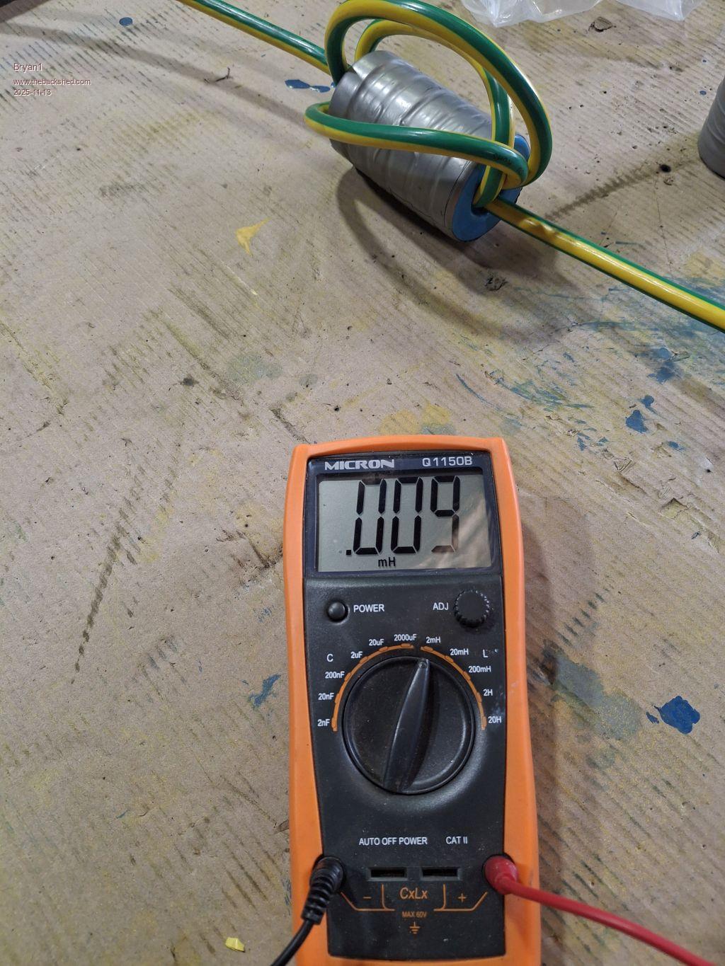 We didn't bother winding the second one and I do have plenty of 35sqmm cable here to play with, just that it's green/yellow as that what we used. The 35sqmm welding cable has a double insulation and 2 turns will be a test so that why we went with the earth wire. |
||||
| The Back Shed's forum code is written, and hosted, in Australia. | © JAQ Software 2026 |
