
|
|
Forum Index : Microcontroller and PC projects : CMM2 Custom Case Project Idea
| Author | Message | ||||
| Twiggy Newbie Joined: 30/08/2021 Location: CanadaPosts: 5 |
Hi, I am new here but I have been active in the vintage computer community, as well as the general computing and technology community for years and years, including taking tech and programming classed in high school, and college, etc. I came to learn of the Color Maximite 2 a few days ago, and after reading about it, and watching a series of reviews, I have decided that I want one for myself. However one thing I don't like about it, is that unlike computers like the Commodore, ZX Spectrum, etc, etc that it was inspired by it does not have a keyboard built-in. So I figured I will make my own custom case with a keyboard "built-in" and I'll make it out of wood as well, to make it look truly DIY. I also decided that I will include speakers built into the case as well. Making the case itself should be simple enough, a rectangular box out of wood is child's play, I have also already found a solution for the keyboard, and that is simply to remove the guts from a cheap mechanical keyboard, and screw it onto the top of the case, and drill a small hole for the USB cable to route through. I think I am going to go with the assembled RetroMax board from Circut Gizmos, because 1) it has a spot for a 3pin audio header which will come handy for the built-in speakers and 2) a bare board without a case is more suited to my needs. Speaker wise, I know I will need a 3pin audio header to solder onto the board, a 3pin audio cable, a small amp circuit which will take a 3pin audio cable, a power source for the amp, and lastly small speaker drivers, probably between 2.5 and 3 inch. This all seems fairly straight forward and doable, it's just a matter of finding the correct parts. It seems like this little amplifier board has all I need and it's cheap too: https://www.ebay.ca/itm/193858194747?_trkparms=aid%3D111001%26algo%3DREC.SEED%26ao%3D1%26asc%3D20160908105057%26meid%3Dba66d98f0f7a4c3b9fdb6a5ae3147dcd%26pid%3D100675%26rk%3D2%26rkt%3D15%26sd%3D144148125094%26itm%3D193858194747%26pmt%3D1%26noa%3D1%26pg%3D2380057%26brand%3DUnbranded&_trksid=p2380057.c100675.m4236&_trkparms=pageci%3A20c51c3b-0968-11ec-bc01-825d6f91073a%7Cparentrq%3A96118ad017b0ab9667b35d34ffef7728%7Ciid%3A1 For power I think I'll use an 18650 battery since I have a few of those lying around, I'll just need to get an 18650 battery terminal so that I can easily remove, recharge, and replace the battery when it dies. I will also get a switch to integrate into the amplifier/speaker circuit, so that my battery won't be being drained when the speakers are not in use. I think theoretically, all should work. However I have never done anything like this before, and I don't have much experience at all working with wires and circuits and such. So, if anyone has any comments, or recommendations they would be welcomed. |
||||
| Mixtel90 Guru Joined: 05/10/2019 Location: United KingdomPosts: 8911 |
Not for the CMM2, but I made a keyboard case out of foamboard for a Raspberry Pi. The keyboard was a bluetooth one simply because I already had one. :) Foamboard and hot glue can be fun, but mounting things onto it requires some lateral thinking sometimes. Mick Zilog Inside! nascom.info for Nascom & Gemini Preliminary MMBasic docs & my PCB designs |
||||
| Geoffg Guru Joined: 06/06/2011 Location: AustraliaPosts: 3362 |
That is a neat little amplifier but why do you need a battery? You could power it from the 5V used to power the CMM2. If you want to power the whole CMM2 + amplifier from a battery you would be better using a power bank of the type used to charge mobile/cell phones. They have a good capacity, include the charger, deliver 5V and are cheap. However powering the CMM2 from a battery does not make much sense as the monitor would need mains power. Geoff Geoff Graham - http://geoffg.net |
||||
Cyber Senior Member Joined: 13/01/2019 Location: UkrainePosts: 161 |
Small VGA monitor could be powered from additional 12V battery (like in UPS) but overall construction would turn out pretty heavy. ) |
||||
| Cyber Senior Member Joined: 13/01/2019 Location: UkrainePosts: 161 |
On the other hand, since you are comparing your idea to Commodore and ZX Spectrum, I don't see a need for battery. Just power both CMM2 and amplifier from the same AC/DC power supply i.e. power brick, like Commodores and Spectrums did. Just make sure you have enough amps. By the way I'm using the same amplifier, it works like charm for a small home needs. |
||||
| Twiggy Newbie Joined: 30/08/2021 Location: CanadaPosts: 5 |
From what I understand there is only one USB port on the CG board, and that will of course be used by the keyboard. Perhaps you mean to power it from the board itself? If so, how would I do that? This is where my lack of experience with pcbs, soldering, and circuits comes in. I'm more used to replacing drives, cards, ram, etc, in PCs and Macs, even though some of them can get very old, like 286 and even 8088 based machines. |
||||
| Mixtel90 Guru Joined: 05/10/2019 Location: United KingdomPosts: 8911 |
It looks like that amplifier module has a switch on the volume control. That's one hole less to bother about. :) Mick Zilog Inside! nascom.info for Nascom & Gemini Preliminary MMBasic docs & my PCB designs |
||||
| lizby Guru Joined: 17/05/2016 Location: United StatesPosts: 3784 |
I've used that amplifier on an F4. Works well when already turned on to a low level when powering up the F4, but will power-cycle the F4 if turned on when already running, and if you turn up the volume too far. Note for future reference that the reason your post extends so far off the screen to the right is because of the long URL. You actually don't need anything from the "?" on, e.g. https://www.ebay.ca/itm/193858194747 Or if you used the globe+link icon (fourth from the left), you get a clickable link: PAM8403 Amp ~ Edited 2021-08-30 22:05 by lizby PicoMite, Armmite F4, SensorKits, MMBasic Hardware, Games, etc. on FOTS |
||||
| Geoffg Guru Joined: 06/06/2011 Location: AustraliaPosts: 3362 |
Easy. The Retromax has a standard 40 pin I/O connector (see the CMM2 manual for the details) which supplies Ground and +5V. Run two wires from these pins to your amplifier. You can solder the wires to the underside of the Retromax or use jumpers like these which will push onto the Retromax's I/O pins. Geoff Edited 2021-08-30 22:07 by Geoffg Geoff Graham - http://geoffg.net |
||||
| Twiggy Newbie Joined: 30/08/2021 Location: CanadaPosts: 5 |
Ah thanks for the information, I didn't know that was possible. I will use jumpers then. |
||||
CircuitGizmos Guru Joined: 08/09/2011 Location: United StatesPosts: 1427 |
Below the sea-of-holes on the RetroMax are unpopulated connections to Gnd, 5V, and 3.3V. 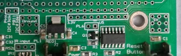 Micromites and Maximites! - Beginning Maximite |
||||
| Twiggy Newbie Joined: 30/08/2021 Location: CanadaPosts: 5 |
Thanks everyone who commented so far, glad I posted this, or I would not know about the onboard power options of the RetroMax. |
||||
| The Back Shed's forum code is written, and hosted, in Australia. | © JAQ Software 2026 |
