Posted: 06:25pm 19 Nov 2026 Copy link to clipboard
karlelch Guru
Hi,
I am interested in robots - driven by MMBasic - and I am currently working on a new version: A hexapod with 3DOF per leg that uses serial servos (12 V Waveshare ST3215 HS). I have a library written in MMBasic that can control all 18 servos and make the robot walk. But currently I am using a bench power supply. Eventually, I want to become mobile with a LiPo battery.
I have mainly experience with "normal" servos and their power draw. I used Claude to work out the specifications of a power control board with the following requirements: - 2x connectors for serial bus input from a Waveshare Bus Servo Adapter - 6x connectors to a chain of 3 servos each (for the 6 legs) - a XT60 connector for the LiPo - a fuse - a soft-on circuit that can be controlled by a microcontroller (PiCo2) - there will be an external power switch between the battery and the board
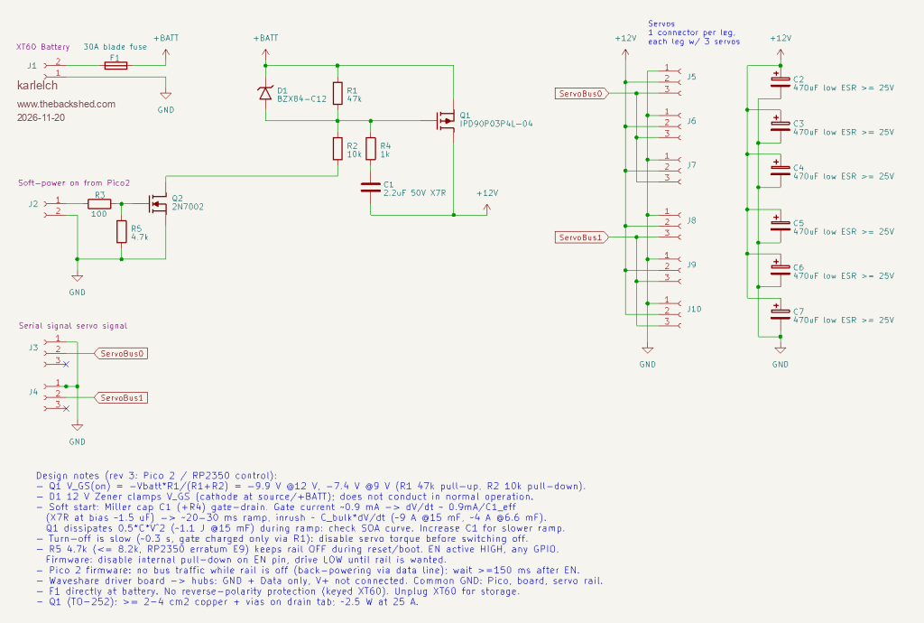
This is what Claude generated (edited for clarity by me):
Anyone experience with such circuits? Could that work?
Thanks Thomas
Posted: 07:10pm 19 Nov 2026 Copy link to clipboard
Mixtel90 Guru
I have no experience with servos whatsoever, but from an electronics point of view I would say that that circuit makes sense.
Making the J2 input high causes the battery to be connected to the servos and the bank of 470uF capacitors. This supply will ramp up, not switch on suddenly. When the servos operate the current is supplied initially by the capacitor bank, the capacitors recharging from the battery while the servos are stationary.
Commands from the two servo control signals are merely paralleled across three servos each so the three will move together.
Taking the J2 input low again disconnects the battery from the circuit. There will be residual charge in the capacitor bank, I suppose, but that doesn't matter.
Posted: 08:47pm 19 Nov 2026 Copy link to clipboard
phil99 Guru
For soft start I think C1 + R4 are placed incorrectly. For a simple resistive load they would work as they are but when the battery is first connected the capacitor bank is at 0V with just a few milliohms resistance. I think they should go from gate to source (+BATT) and C1 may need to be bigger. Q1 could still get hot as the capacitor bank charges so a heatsink with thermal mass (thick aluminium or copper) may help.
Currently they will momentarily turn Q1 fully on as soon as the battery is connected. The peak current into the capacitor bank might be enough to damage Q1 or the battery before the fuse has time to blow. Edited 2026-11-20 07:38 by phil99
Posted: 10:35pm 19 Nov 2026 Copy link to clipboard
Mixtel90 Guru
It's a circuit to model, but not tonight.
Because the cap bank is discharged the lower side of C1 is also low. For Q1 to turn on the gate has to get low enough. C1 is already charged to 12V via R3 so the gate is held up by that voltage via R4. C1 now has to discharge via (R2+R4) to (12-Vgs) before Q1 opens. R2 and C1 are fairly high so this will take a little time. True, Q1 will start to dissipate as soon as Vgs is exceeded, but that may not be for long at that point.
Posted: 11:30pm 19 Nov 2026 Copy link to clipboard
phil99 Guru
Not when you first plug the battery in. Then C1 has 0V across it, briefly pulling the gate low through the capacitor bank.
For modeling put a switch in the battery line and see what the peak current is when you close it. Maybe it is possible to also see how much energy is in the pulse that the MOSFET must absorb. That should reveal whether it is a problem or not. Edited 2026-11-20 10:00 by phil99
Posted: 08:56am 20 Nov 2026 Copy link to clipboard
Mixtel90 Guru
Good point - I hadn't looked at when the battery is first connected. I reckon you've got almost 100ms of virtually dead short across the battery. That's not good...
As I've said, I have no experience of servos. Are the caps even necessary? They are motors, not solenoids. The impedance of a LiPo battery is very low. A good mosfet will have RDSon of 50mΩ or even less. The tiny little SOT23 AO3140 for example can manage that with Id of 4A. Just don't look for TO92 packages that can do anything useful.
. Edited 2026-11-20 18:57 by Mixtel90
Posted: 09:20am 20 Nov 2026 Copy link to clipboard
karlelch Guru
Thanks Mixtel90 and Phil99!
These are digital serial servos; they listen to a simple 1-wire serial bus for packages and respond to their ID. But I agree, the labelling of two serial busses is confusing, because the Waveshare board which translates the COM signals of the Pico2 to the servo bus signals has two connectors with the bus shared.
I wanted to switch to these servos because they can respond to complex motion commands and report on their status, such as position, current, voltage, temperature, load ...
That'd be great! I have no experience with that ...
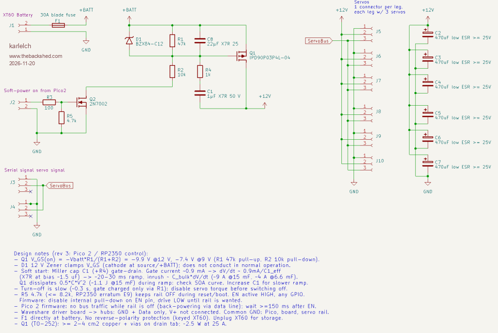
Thanks for this hint. I gave it back to Claude and it agreed, but suggested a different solution: An additional C8 between source and gate and a different value for C1:
I am wondering that too. This was a recommendation by Claude. The servos are said to feature local voltage regulation, and all sorts of protection (overcurrent, overvoltage, and thermal shutoff), though it is hard to get a circuit diagram.
Best Thomas
Posted: 09:50am 20 Nov 2026 Copy link to clipboard
phil99 Guru
The circuit looks good now.
With all that perhaps 47 to 100µF close to each servo will be enough.
Posted: 10:05am 20 Nov 2026 Copy link to clipboard
karlelch Guru
Thanks - yes, I'll try that.
Best Thomas
Posted: 10:30am 20 Nov 2026 Copy link to clipboard
Volhout Guru
Hi,
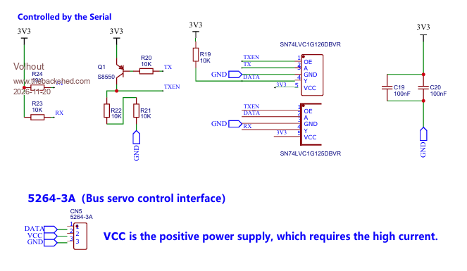
The pinout on the servo connectors is wrong (1-3 swapped). See :
Not sure you need all the 470uF E-caps. The battery is low impedance, the FET is only 4 mohm. Maybe one is sufficient. Just to get rid of the short spikes. One 470uF may be better that 6 small ones (ESR wise).