Menu
JAQForum Ver 19.10.27

Forum Index : Electronics : Bryan's Inverter build

   Page 25 of 25    
Posted: 06:12am
02 Apr 2026
Copy link to clipboard
Bryan1
Guru


Now thinking back to my last test after I put all those scope pic's up with no replies I did think everything was right  

I had the power supply set to 26 volts 400mA current and the voltage did rise to around 160volts AC then a click click click coming from the power board. The AC voltage dropped to zero and the power supply was drawing the full 400mA.

So the question after the AC voltage was ramping up why did it fail and go that clicking sound as the board has passive parts.
 
Posted: 07:24am
02 Apr 2026
Copy link to clipboard
phil99
Guru


  Quote   that clicking sound
My guess is it is that bank of big caps suddenly discharging when something reaches it's breakdown voltage. The caps recharge at the current limit until the cycle repeats.

To see if this is the case reduce the current limit to slow the recharge down and monitor the voltage across the caps. It should slowly rise then suddenly fall.

  Several times KeepIS said  You cannot power up an inverter with a fault with 60000uf of CAPS in circuit - PERIOD!


They can discharge thousands of amps into a short which means your power supply current limit gives no protection at all.
Remove them until all faults have been found.

E = 0.5 * C * V^2 where E = energy (Watt Seconds), C = Farads, V = Volts

E = 0.5 * 0.06 * 26^2 = 20.28 Watt Seconds

So if the discharge lasts 1mS that is a 20kW pulse! More than enough to destroy MOSFETs etc.

(If the discharge lasts 0.1mS that is a 200kW pulse!)
Edited 2026-04-02 17:28 by phil99
 
Posted: 07:36am
02 Apr 2026
Copy link to clipboard
Revlac
Guru


I thought it looked ok too, but I never measured (this test inverter on the bench) that way, now at 23vdc and 400mA I get 144vac on this one, not sure why yours was clicking unless its the power supply limit and the invert wants more to reach 230vac?  See the photo of it working 2 pages back.
Edit: last photo is the working one.

Was it the power supply clicking and the inverter is still ok or is something shorted again?
Edited 2026-04-02 17:41 by Revlac
 
Posted: 07:57am
02 Apr 2026
Copy link to clipboard
Godoh
Guru

I remember when Oztules was about that he always suggested removing the capacitors when testing a repaired board.
That is the process I used when fixing my Powerjacks when they blew up.
Took the caps off the board
replaced mosfets and sometimes drivers
test board, if it works then put capacitors back on and cross fingers
 
Posted: 08:21am
02 Apr 2026
Copy link to clipboard
mab1
Senior Member

  Bryan1 said  Well just sacrificed another 4 mosfets   soldered one on each leg then set it all up turned it on saw the AC voltage rise to 168 volts then a tick tick tick started on the power board which caused the lcd to flicker so that the end of trying to get this inverter to work as I do think the power board is shot.


Well the scope waveforms seem ok.

I assume this was on the bench psu?
What did you have the current limit set to?

Just thinking that the clicking/flickering display could be the result of hitting the current limit of the psu rather than a fault - if the current draw > the psu limit the voltage would drop, possibly causing the driver board to stop and restart. but it would be helpful to know what the current limit was set to at the time.
 
Posted: 12:30pm
02 Apr 2026
Copy link to clipboard
tinyt
Guru

  Bryan1 said  Now thinking back to my last test after I put all those scope pic's up with no replies I did think everything was right  


Those scope pics look OK. I was too busy with other things and was not able to reply. Apologies.

It would also help to post exactly where the scope probes are connected.
Edited 2026-04-02 22:33 by tinyt
 
Posted: 10:43pm
03 Apr 2026
Copy link to clipboard
Bryan1
Guru


Ok with a fresh start decided to set the board backup and this time I set the power supply to 800mA  

They do say a picture is a thousand words  


So looks like it was the power supply was set too low
Edited 2026-04-04 08:55 by Bryan1
 
Posted: 11:16pm
03 Apr 2026
Copy link to clipboard
Bryan1
Guru


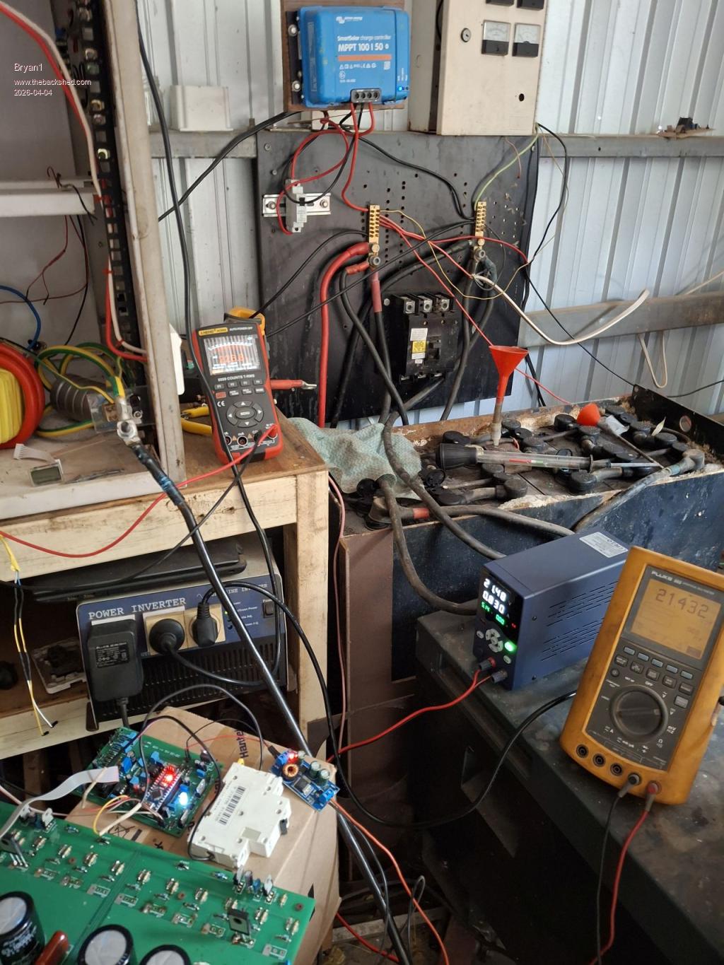
Now that first test was with the AC output disconnected from the AC board so I could see if the AC voltage was right.

Connected the toroid AC outputs back onto the AC board and finally the energy meter came to life


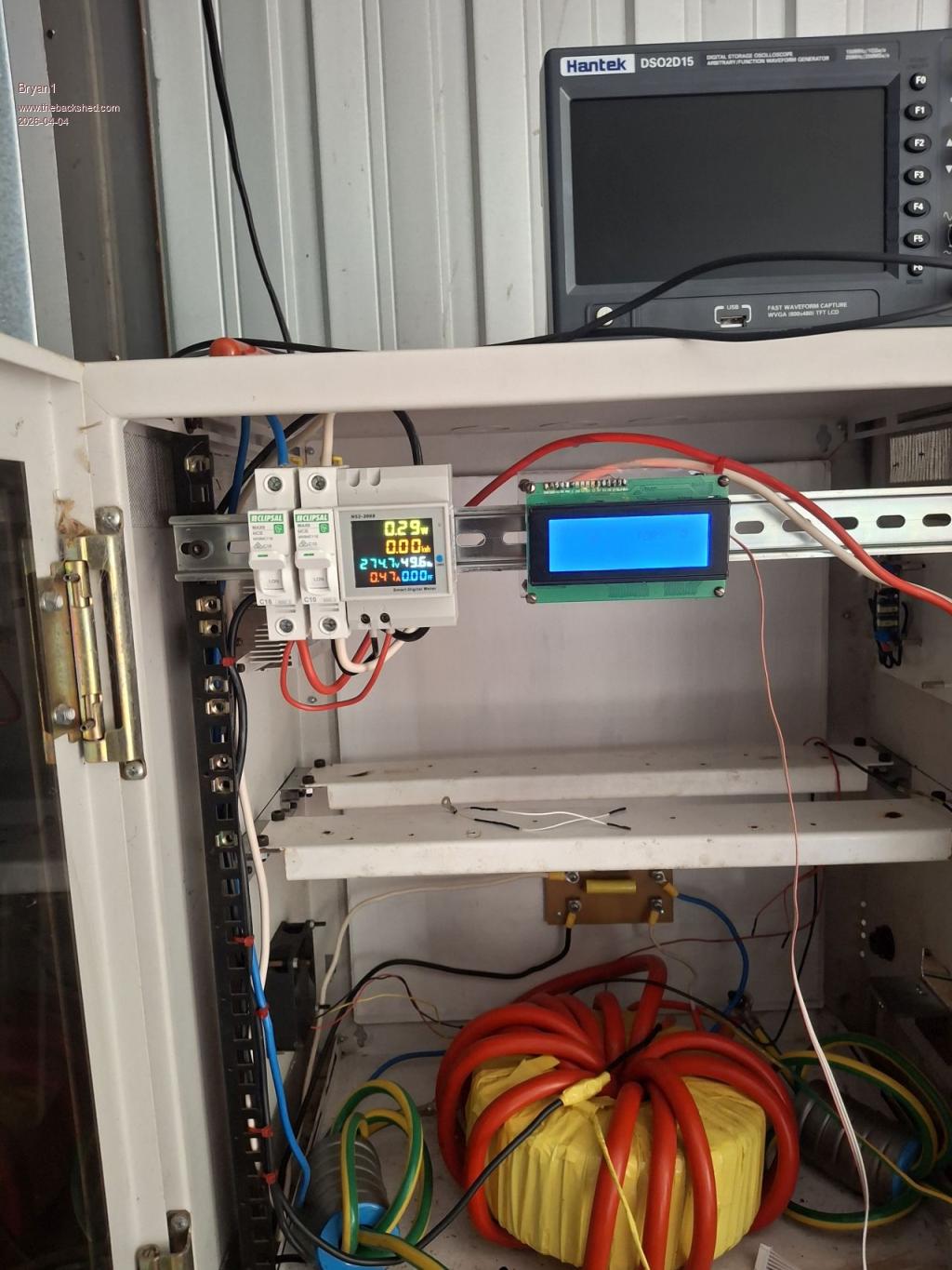
One happy camper and a huge Thank You for all the members that have helped me with this inverter project.

Now with that Ali inverter board it can become one piece of the puzzle for wiring up my shearing shed.

Edit: as the voltage was 274AC I shut it down and let the caps discharge, set the power supply to 4 amps and hooked up the VFB wires and turned it back on. Saw the AC voltage was 120 volts so used the trim pot to adjust the voltage to 230V AC  

One thing I do need to do is set that Vbat option in the code as it's 0.5 volts over the Vbat and trying to get that magic number is proving to be some fun.
Edited 2026-04-04 09:47 by Bryan1
 
Posted: 12:44am
04 Apr 2026
Copy link to clipboard
Bryan1
Guru


Ok found that magic number 0.05860 got the BV on the lcd showing 26.0 volts  

Now the energy meter is showing 231 volts AC and 0.39 amps and the power supply is set on 26 volts with a 0.760 the average current reading.

So may be time to put the rest of the mosfets on the board and install the inverter in the box but in no hurry as this has taken so long to get right.
 
Posted: 02:18am
04 Apr 2026
Copy link to clipboard
Bryan1
Guru


Ok so I do think we need to see the AC waveform which is a totally new thing for me using a scope.

It has been said one would need a wall wort or a small transformer when we already have one on the AC board being the 12Vac for the VFB.

So hooking a probe the diode on the brainboard where VFB comes in but where would the ground go?

I have tried googling this and not finding the right answer I need.
 
Posted: 02:46am
04 Apr 2026
Copy link to clipboard
tinyt
Guru

  Bryan1 said  Ok so I do think we need to see the AC waveform which is a totally new thing for me using a scope.

It has been said one would need a wall wort or a small transformer when we already have one on the AC board being the 12Vac for the VFB.

So hooking a probe the diode on the brainboard where VFB comes in but where would the ground go?

I have tried googling this and not finding the right answer I need.


Your 'scope manual says:


So, to play safe, I would use another 230vac:12vac isolation transformer and connect its 230vac to the inverter 230vac output. Then the scope probe tip and probe gnd to the 12vac output of this transformer.

Edit; If you have a battery operated 'scope to use, then there is no need for this second isolation transformer.
Edited 2026-04-04 12:49 by tinyt
 
Posted: 03:25am
04 Apr 2026
Copy link to clipboard
Bryan1
Guru


Thanks that TinyT I found an old transformer so hooked up a power cord and did the first test with my DMM, 29 VAC with the 240 volt coming from my Kipoint inverter.

So hooked up to the inverter


Regards Bryan

This is the transformer I used


Edited 2026-04-04 13:32 by Bryan1
 
   Page 25 of 25    


To reply to this topic, you need to log in.

The Back Shed's forum code is written, and hosted, in Australia.
© JAQ Software 2026