Forum Index : Electronics : Recovering from disaster by using Wiseguy's mosfet driver design
Page 3 of 3
Posted: 01:29pm 01 Oct 2025 Copy link to clipboard
tinyt Guru
Measurements are in the inverter at the points shown in red.
You are probably correct about the waveform distortion with load and without load which affects where the EG8010 is sampling it.
It is not the duty cycle I just labeled it spwm, it is the ac voltage reading from the fluke DMM, see figure above.
Thanks. It is a rat's nest inside and it is still a work in progress. I am still struggling with the arduino coding for all monitoring and controls.
And I also still have to learn how MQTT and Home Assistant work. Edited 2025-10-02 01:15 by tinyt
Posted: 05:33pm 01 Oct 2025 Copy link to clipboard
analog8484 Senior Member
Thanks for doing the measurements. So, the main takeaway for me is that it's possible to achieve very high surge power with a relatively small/lightweight transformer core with a little larger winding gauge and a ~2x power stage board. This is encouraging.
Posted: 05:46pm 01 Oct 2025 Copy link to clipboard
tinyt Guru
Maybe it also has to do with core material and it being a toroid. I am only guessing, I am just an experimenter. Edited 2025-10-02 03:47 by tinyt
Posted: 11:28pm 01 Oct 2025 Copy link to clipboard
KeepIS Guru
I was also initially surprised that just a single 2kW AeroSharp Toroid, using the existing 230vac winding and a 27 turn 4-gauge primary winding could easily start large induction motor surge loads, without apparent signs of waveform saturation.
Huge loads like the one that blew the FETS in this thread, are obviously going to expose the slightest weak spot in the complete Inverter chain.
I mean right from the quality of the sourced components (FETS) to every connection and connector and cable in the DC supply path to the FET terminals.
Any hidden instability in layout and any weak point in the AC and filter connections and filter design right up to the Load.
And the big one - Choke saturation, should it/they fully saturate, from what I have read, this has the potential to suddenly double (or more) the FET current under these huge surge loads in an Inverter.
I have no desire to test this though _ Edited 2025-10-02 09:30 by KeepIS
Posted: 12:43am 02 Oct 2025 Copy link to clipboard
tinyt Guru
Just an FYI update: The power board is fixed. All 24 mosfets were replaced together with their totem-pole drivers. Two gate drive diode 1N4148 were tested to be shorted and they were also replaced. It is now running and the voltage readings I posted earlier were taken from the inverter with this power board.
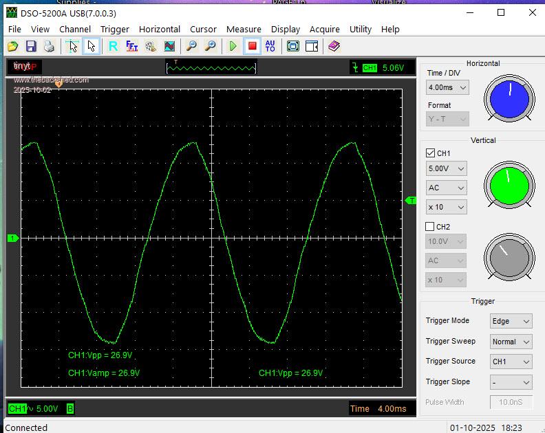
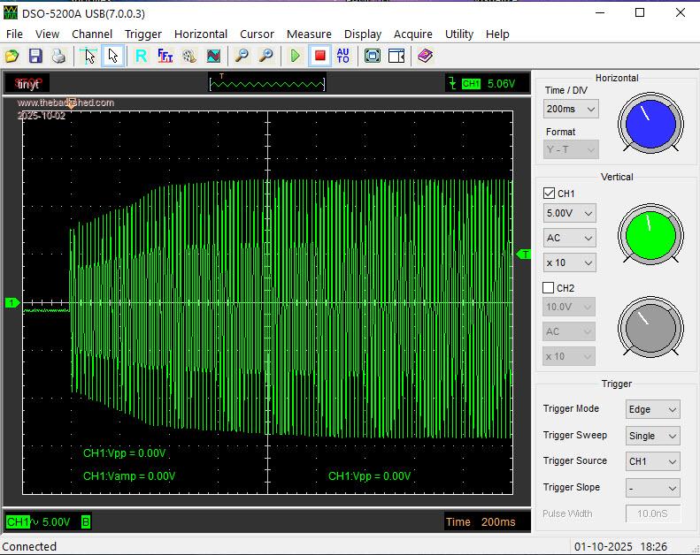
The soft-start module came and I tested it using a small step-down transformer for the load. Input is grid(mains/street power). The scope probe is at the low voltage section of the transformer. Trimpots on the module were re-adjusted for arbitrary start-up voltage and ramp delay.
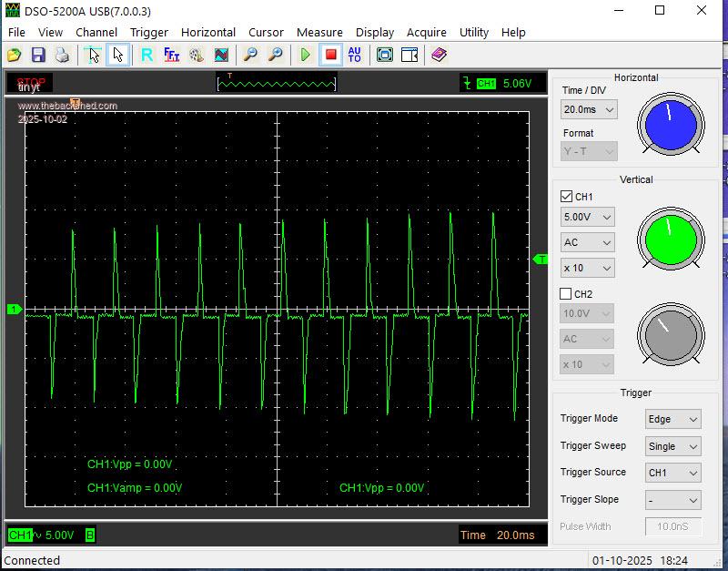
Edit: Earlier pictures that showed zero crossing anomaly is no longer present with additional heating element load in parallel with the small transformer. Pictures are now replaced.
(Output waveform after delay in the first picture shows triac zero crossing discontinuity?) <- No longer relevant.
(I think the delayed bypass relay is really needed so that the compressor will not run with this zero crossing anomaly.) <- No longer relevant.
Will test it using my small air compressor induction motor later. Edited 2025-10-02 11:40 by tinyt
Posted: 04:08pm 02 Oct 2025 Copy link to clipboard
analog8484 Senior Member
That's another good data point.
Good point. Tinyt also has quite a few choke cores in his inverter.

.jpg)