
| Menu | JAQForum Ver 26.09 |
| Menu | JAQForum Ver 26.09 |
Forum Index : Electronics : Na Balancer
Hi All Long time no posts from me. Below a schematic of a Sodium Ion Cell Balancing circuit. Showing it simplified to get some opinions on a problem. The switches are all OptoMos Relay modules capable of 20 Chinese Amps. OptoMos Maximum I will put through is 5 A PWM at 5v. The 5v is from an isolated PS, but has not been connected yet, until I am 100% confident. So perfected the software to measure the Cell voltages and switching the Relays to select the Cell to be balanced. By switching say SW0A & SW0B together (they are hardwired together) the path of the current from the +5v iso rail connects through to the 0v iso rail. That is 100% guaranteed correct and problem free. Been testing with NO iso 5v connected, no load current at all. When I connected my ESP32-S3 to my laptop, predictably I got some erratic readings from the cells due to powering my ESP32 and ADS1115 from the laptop only. However, there was never a problem during this period. Then I decided to use a 240 to 5vdc PS to get a more stable reading and that also worked perfectly. (for about 10 minutes) I had both Laptop USB and the extra PS connected. There is a schottky diode in between as specified on the ESP32-S3 doc's. Then for some reason the SW2A started smoking. The only way to stop it was to disconnect the PS. I can guarantee that the only Relays being driven were SW0A & SW0B. There are led's on the 3.3v o/p's. It took out the ADS1115 as well. My areas of doubt are; The ADS1115 is connected to the NON-Isolated 5v supply When balancing Cell 0 the 0V isolated & 0V NON-Isolated are connected. Would love to hear some opinions on this. 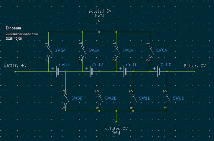 Regards Hervey Bay Qld. |
||||||
Hi All A total picture of the system. 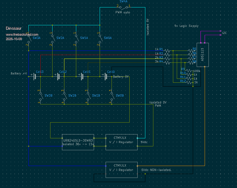 |
||||||
Way down the bottom of the Aliexpress link it says not for PWM control, on / off only. The 1.5ms turn on time and 1ms turn off would be problematic anyway for anything other than very low PWM speeds. Edit - ignore me, you're just using the relay modules to connect the 5V PWM, not PWM'ing the modules themselves if I'm seeing it correctly. Edited 2026-10-08 15:55 by FET cemetery |
||||||
Hi All Yes I was aware of that, but when testing them at 120Hz, they behaved without any problems.It was a nice square wave. I also have a 10mSec delay between cells when I change cells. |
||||||
Hi All In case someone is interested; The design below works perfectly to balance LiPo4 or Na-Ion Cells. You can choose to balance with as little or as much as the Cell will tolerate. Most commercial balancers quote Amperage that slows to a crawl when it gets close to Cell V. I am pushing 5.5A in as it takes about 15 sec to increase by 1 mV, so plenty of time to stop the balancing.It took 4 hours to balance all cells within 2mV from 50 mV. The parts are: OptoMos modules on I2C ; Although rated at 20A , I would NOT put more than 8 A through. They are very reliable but all the experimenting I did, meant de-soldering and ususally the 3 pin header via's failed after that. So, I ended up buying new ones. The 2 OptoMos relays for each cell are stacked on the same 3 pin header, so they are fired at the same time. Ideal Diode Modules; soldered inline and shrink sleeved) Some negative comments on line , but have not experienced any. Fast Blow fuses; M205 x 8A None of the above went beyond 32 C with a 25 C ambient. That will change once the whole lot goes in the camper out bush. 0.1 ceramic caps; These are recommended to stop spikes to the OptoMos and the ADS1115. Power is cycled by turning the Isolated PS ON, then after a settling time the target Cell is connected, same in reverse when I disconnect the Cell, then the PS. With the above I am getting stability of 1 count during Balancing (about 0.15mV). Software safeguards; Verify delay between Cell OFF to Next Cell ON by reading back Relay states. Surge voltage, when connecting to a Cell it is typically between 7 to 10 mV. But is taken into account when evaluating the balance state. The drop in V is usually about 80% of the surge. Code written in C in Espressif environment. Using Wifi Hotspot with netcat; I send a line of text every 15 sec if phone or Laptop is listening. The wires from the ADS1115 MUST be separate from the power cables to the Cell studs, as the voltage drop at balancing stuffs up the readings. 15 - 30 vdc can be sourced from the Solar cells or the battery itself. A good alternative for grid charging is a Laptop PS, as long as it is double insulated and does not have an earth pin. I set the CC / CV converter firstly to about 10 vdc, then adjust the CC to my target current (5.5A). Once I am happy with that, screw the voltage pot down until the current starts to drop, then back up a bit. Regards 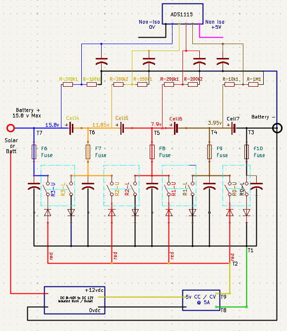 |
||||||
 |
The Back Shed's forum code is written, and hosted, in Australia. |


