| Menu | JAQForum Ver 19.10.27 |
| Menu | JAQForum Ver 19.10.27 |
Forum Index : Microcontroller and PC projects : PicoMite V6.01.00 betas
I can answer your question about the typo that was fixed (and save Peter the effort). The 'if' statement below with the typo was guarding the next decode of VT100 Escape codes. The reason it was in the code unnoticed for so long is well behaved terminal programs never send anything outside the expected value of 1 to 6 after the ESC [. ESC [ 1 ~ is generated by the Home key. ESC [ 2 ~ is generated by the INSERT key. ESC [ 3 ~ is generated by the DEL key. ESC [ 4 ~ is generated by the END key. ESC [ 5 ~ is generated by the Page Up key. ESC [ 6 ~ is generated by the Page Down key. if (c < '1' && c > '6') { c1 = '['; c2 = c; return 0x1b; } // the 3rd char must be in this range while ((tc = getConsole()) == -1 && InkeyTimer < 70) ; // delay some more to allow the final chars to arrive, even at 1200 baud if (tc == '~') { // all 4 char codes must be terminated with ~ if (c == '1') return HOME; if (c == '2') return INSERT; if (c == '3') return DEL; if (c == '4') return END; if (c == '5') return PUP; if (c == '6') return PDOWN; c1 = '['; c2 = c; c3 = tc; return 0x1b; // not a valid 4 char code } You will notice the code is time sensitive and will wait for the next expected character to arrive. If the terminal gets bogged down, and doesn't send all the characters as a burst, it is possible for the InKey() code to think the Escape Sequence isn't going to be completed and give up. That may factor into your seeing ~ and [ characters showing up on the screen. They are part of a normal VT100 Escape Sequence but if the sequence gets interrupted, they can be interpreted as just normal displayable characters. Edited 2025-09-23 08:39 by EDNEDN |
||||||
Peter, This is the code you published 1 year ago as a demo for fast sampling 2 ADC's. (I just added comments, so I could understand what it does). In the video you published, and also on the screen of my unit, in the top left corner I observe pixels changing (in white). As if something is writing directly into video memory. This is independent of the screen (I have a version that works on LCD that shows the same). Lower ADC sampling speed also makes no difference. At 100kHz the effect is the same. Is this a side effect of the LINE GRAPH command ? Is it "harmless" ? Again, this existed 1 year ago, so it is not something changed in the last revisions. 'Peters code for a 2 channel oscilloscope 'todo : check if wiping traces by re-drawing black is faster than CLS CLS FRAMEBUFFER create FRAMEBUFFER write f 'memory allocation and fill default X axis locations Dim float a(1279),b(1279),aa(639),bb(639),c(639),d(639),e(639) For i=0 To 639:e(i)=i:Next 'open ADC for maximum clock speed (378MHz CPU) ADC open 1968750,2,done 'main loop Do 'start sampler ADC start a(),b() 'wait for ready Do Loop Until f%=1 f%=0 'this assumes a trigger in the first half of a() p%=Math(crossing a(),1.5,-1) 'a trigger 'copy 640 points from a() to aa(), similar b() Memory copy float Peek(varaddr a(p%)),Peek(varaddr aa(0)),640 Memory copy float Peek(varaddr b(p%)),Peek(varaddr bb(0)),640 'scale to 3.3 x 50 = 165 pix vertical Math scale aa(),50,aa() Math scale bb(),50,bb() 'add vertical location on screen Math add aa(),50,aa() Math add bb(),250,bb() 'wipe old traces Line graph e(),c(),0 Line graph e(),d(),0 'draw new traces Line graph e(),aa(),RGB(green) Line graph e(),bb(),RGB(cyan) 'show on screen FRAMEBUFFER copy f,n 'copy current, for wiping later Math scale aa(),1,c() Math scale bb(),1,d() Loop Sub done f%=1 End Sub Volhout |
||||||
2040 or 2350 or both? |
||||||
Hi Peter, Attached file, both 2040 and 2350 with ILI display attached, shows the problem. Which is strange, since this has a framebuffer L (overlaying this part of the screen with the non-transparent color yellow) and it is bleeding right through L. But in the earlier version, that did not have framebuffer L, it also shows. So it is not tied to L, but also not to F, and since this is LCD, it is also not tied into N. Looks more like an error happening in the merge function. 2ch_scope_demo_Peter2.zip Volhout |
||||||
The issue is that the ADC is overwriting bytes in the framebuffer. If you add a dummy 16 byte variable before a(1279) the problem goes away (e.g.x(1)). I'll see if I can find the issue but in the meantime that is the workaround |
||||||
Thanks, Volhout |
||||||
V6.01.00b15 PicoMiteV6.01.00b15.zip Fixes a bug in ADC START Change to configuring SSD1963 displays Changed configuration command OPTION LCDPANEL controller, orientation [,backlightpin] [,DCpin] [,NORESET][,INVERT][,DB0pin] The new parameter INVERT causes the RGB to be inverted to BGR to suit many displays from BuyDisplay (East Rising) The specific variants SSD1963_5ER_16 and SSD1963_7ER_16 are removed and now you can invert the colours on any SSD1963 variant with both 8 and 16-bit interfaces. As before the DB0pin parameter is only available on the RP2350 for 16-bit displays The complete list of parallel displays supported are: 320x240 ILI9431_16 '16 bit databus RGB565 ILI9341_8 '8 bit databus RGB565 400x240 SSD1963_5_12BUFF '12 bit databus RGB888 SSD1963_5_16BUFF '16 bit databus RGB565 SSD1963_5_BUFF '8 bit databus RGB888 480x272 SSD1963_4 '8 bit databus RGB888 SSD1963_4_16 '16 bit databus 480x320 ILI9486_16 '16 bit databus 800x480 SSD1963_5A '8 bit databus RGB888 SSD1963_7 '8 bit databus RGB888 SSD1963_7A '8 bit databus RGB888 SSD1963_8 '8 bit databus RGB888 SSD1963_5_16 '16 bit databus RGB565 SSD1963_5A_16 '16 bit databus RGB565 SSD1963_7_16 '16 bit databus RGB565 SSD1963_7A_16 '16 bit databus RGB565 SSD1963_8_16 '16 bit databus RGB565 ILI9341_16 '16 bit databus RGB666 IPS_4_16 '16 bit databus RGB565 NB: The 400x240 drivers are buffered with updates taking place on the second CPU and highly optimised (and more so if DB0 is GP0). They use pixel doubling on the underlying 800x480 displays. They should run on any standard 5" SSD1963 display including the BuyDisplay versions (set the INVERT option). They should run any program designed for 320x240 operation (e.g. Petscii) with the image appearing on the left of the screen. The display buffer is RGB332 and supports the MAP command and function to allow any RGB888 colour to be displayed. If there is demand I will also include support for buffered 400x240 operation on 7" and 8" displays and possibly buffered 480x272 for the 4" SSD1963 - let me know. |
||||||
@Peter, Previously using on your 64pin DIL module: PicoMite MMBasic RP2350B V6.01.00b14 and successfully had a 5" IPS from ER running with: OPTION LCDPANEL SSD1963_5ER_16,L,,GP17,,GP1 Just loaded b15 (after nuking, and to clarify: PicoMite MMBasic RP2350B V6.01.00b15) Using the new format OPTION with invert by typing: OPTION LCDPANEL SSD1963_5_16,L,,GP17,,INVERT,GP1 BUT screen not responding. Tried 5A_16 too. Am I doing something stupid? ALSO, is it a big job to add the 4.3" 800x480 too? I was about to see if they sprung to life with b15, but currently need to get the 5" working again..... JUST noticed in option list (on b15) it is reported as: OPTION LCDPANEL SSD1963_5_16, LANDSCAPE,,GP17 i.e. the end bit is missing showing GP1 whereas on b14, it is fully reported as: OPTION LCDPANEL SSD1963_5E_16, LANDSCAPE,,GP17,,GP1 Edited 2025-09-27 20:28 by WhiteWizzard |
||||||
It's perfectly possible I have screwed something up adding the invert option. I'll try and test sometime in the next day or so. Never heard of it. The only 4.3" SSD I know about are 480x272 |
||||||
Here's one: 800 x 480 LCD Screen and here's a cheaper one Cheaper LCD Edited 2025-09-28 02:24 by toml_12953 |
||||||
Neither of those are SSD1963. They may already be supported with IPS_4_16 Updated version for RP2350 which should fix WW's bug PicoMite.zip Edited 2025-09-28 02:52 by matherp |
||||||
That appears to be only for the PCB, without the screen. |
||||||
This one from BuyDisplay @Peter: I can gladly send you one if you’d like to have a unit to play with. Thanks for the ‘fix’ - will try later when back home… Edited 2025-09-28 04:52 by WhiteWizzard |
||||||
No thanks - try it with the various versions already built in and see if anything works |
||||||
Just to quickly confirm that it did fix the issue - Thanks |
||||||
V6.01.00b16 PicoMiteV6.01.00b16.zip Fixes a bug in MAP command when using buffered LCD displays I've added 'usefurtherest` as an option to DRAW3D SHOW and DRAW3D WRITE DRAW3D SHOW n, x, y, z [,nocull][,usefurthest] DRAW3D WRITE n, x, y, z [,nocull][,usefurthest] set 1 to use the furthest vertex and zero (default) to use the centroid for Planters algorithm sorting. |
||||||
Is WebMiteRP2350V6.01.00b16 supposed to work with the Pimoroni Pico Plus 2W? When I type UPDATE FIRMWARE, I get a File Manager screen from the Pimoroni. I send the WebMite file over to it and the directory disappears but after a few seconds, it reappears without the WebMite file listed. I have nuked the flash before attempting the upgrade with the same result. I can successfully load PicoMiteRP2350V6.01.00b16 with no problem but then, of course, I have no access to WiFi. |
||||||
|
||||||
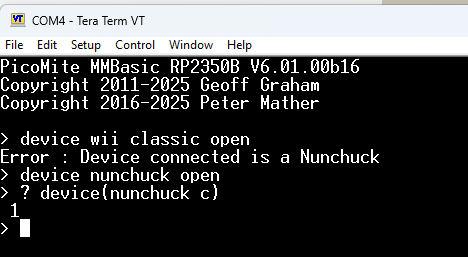
@Peter, Have you ever been able to find out what causes the issue with the 2 WII controllers ? When you open a WII classic, but have a WII nunchuck connected, it gives an error message. When you next try to open a WII nunchuck, it says this is not possible (the channel is open). Closing the classic in between does not help (the channel is already closed). Do the reverse When you open a WII nunchuck, but have a WII classic connected, it gives an error message. When you next try to open a WII classic, that works. I already use a work around (doing the I2C in MMBasic) but I was curious if you ever found out why. I think this was on b11. Volhout |
||||||
 |
||||||
| The Back Shed's forum code is written, and hosted, in Australia. |
