| Menu | JAQForum Ver 19.10.27 |
| Menu | JAQForum Ver 19.10.27 |
Forum Index : Electronics : Recovering from disaster by using Wiseguy's mosfet driver design
So, I started removing the blown mosfets using suction desoldering tool. And I added more damage by tearing the top side copper foil. Luckily, I can beef up the connection at the bottom side. To avoid further copper foil damage, I cut two adjacent legs of the mosfet (my small cutter can reach only two) so that I can easly desolder and pull the remaining leg. I will be replacing all 24 mosfets anyway. 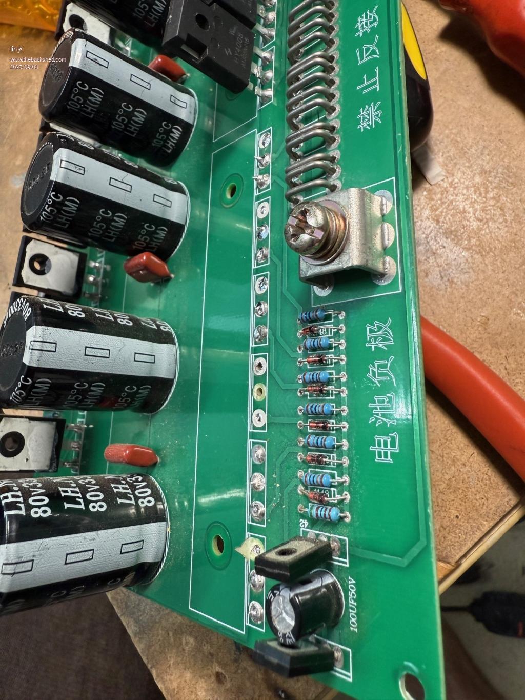 One pair of totem pole transistors also was damaged together with their solder pads. I will be replacing all four pairs. Note also the solder pad damage of the badly blown mosfet. 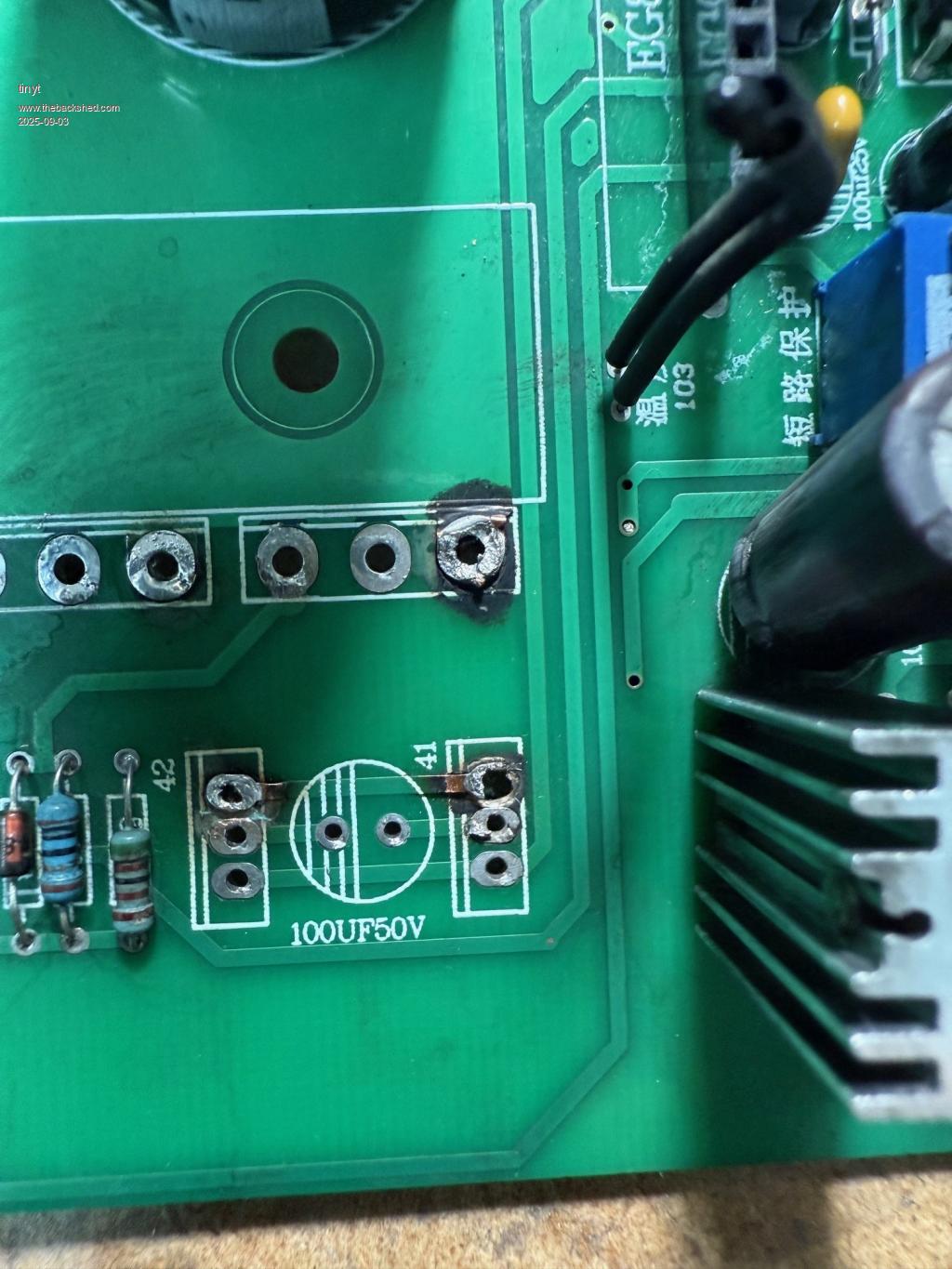 Here is close up of three blown mosfets. The top mosfet shows one of the source terminal bond wire sticking out which measures roughly .013" (.33mm) dia. with a caliper. The bottom mosfet seems to show that there are two bond wires for the source terminal. And apparently their explosion caused the body to crack. 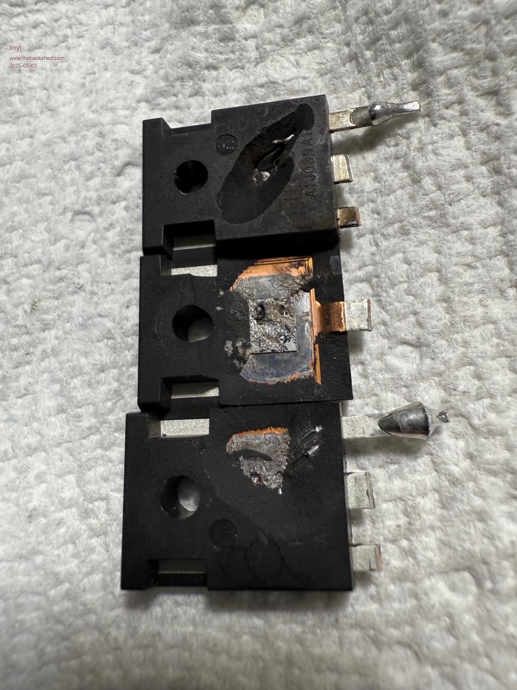 |
||||||
Good luck with the repairs Tiny. That was a pretty good blow up. I hope it all goes well and that you find all the damaged components first time. The box you have the inverter in is very tightly packed, that looks really compicated. There are so many different boards packed in there. Pete |
||||||
It also took out the 48V to 12V buck regulator and opamps. Still testing for more damage. Way back I started a technical manual for my sons when I am gone. But I have not finished/updated it. I think this page is still good except for the auto pre-charge board which is now replaced with a simple pushbutton/power resistor combination. 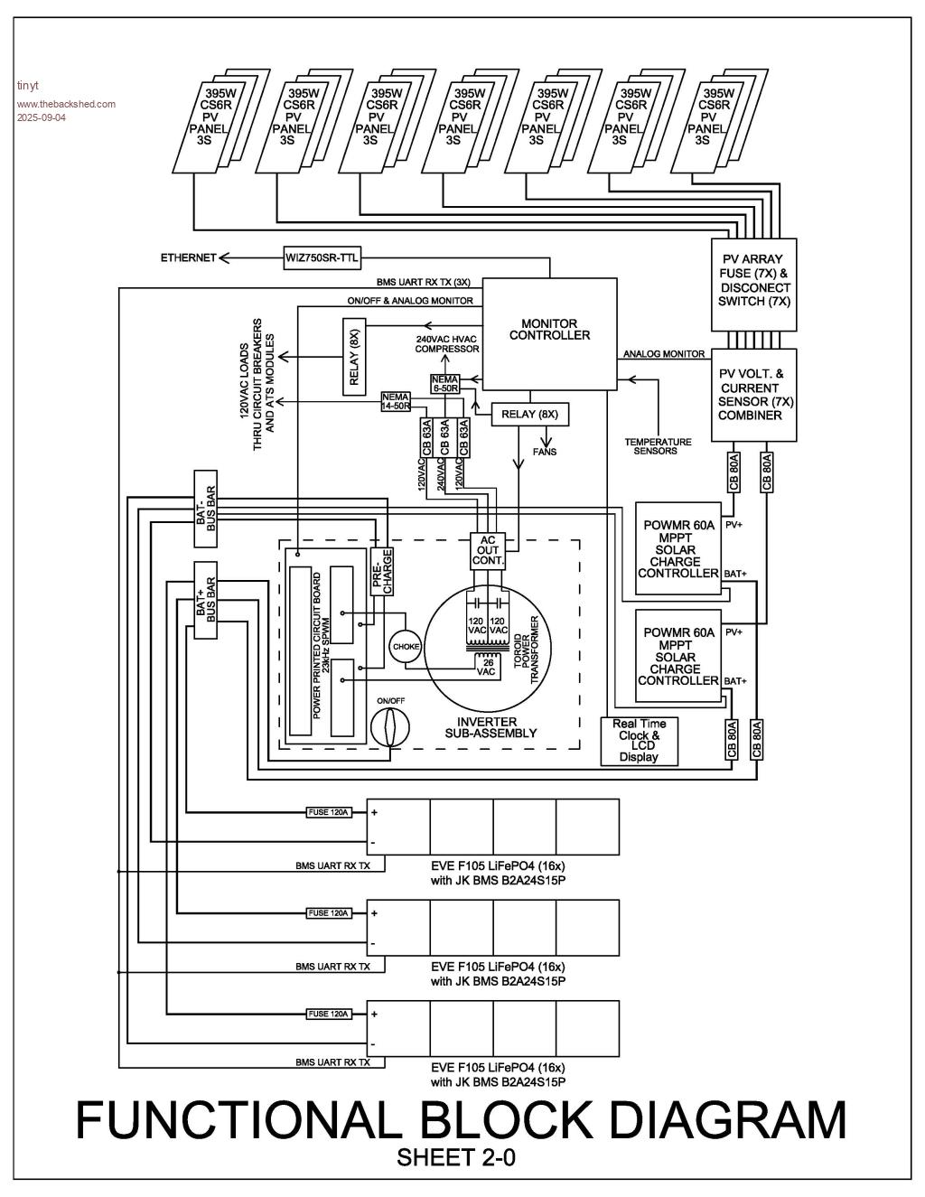 |
||||||
Nice diagram Tiny. I have done similar for my place for the next people who live here after I leave the planet. But my system is very simple, there are a few change over switches so the Grid inverters can feed back through two different battery inverters and there is a system of switching for using the EV charger Plus a voltage controlled relay that switches the GTI inverters off when the batteries are charged. No ethernet Batteries are Valve Regulated Lead Acid, so no complicated BMS. Just 4 regulators for the panels, and two GTI inverters for another two banks of panels. So instructions required for anyone else to know how a system that has grown from 1.2 kw of panels and one inverter, to 10kw plus of panels and 3 inverters. Good luck Pete |
||||||
Tiny, On the Diagram, I'm curious about the CB 80A on the solar charger input..... |
||||||
That is what I had on hand, I don't if it should be lower rated at 60A. But it is mainly used to remove/apply PV power to the SCC. Note that the PV- connections are not shown in that diagram. Edited 2025-09-05 00:06 by tinyt |
||||||
After removing all 24 mosfets and four pairs of totem-pole drivers, I tested to see if the 48V to 12V buck converter circuit is working. Of course it is not. Found shorted components and it took me a while to 'discover' a burned copper trace hidden under a connector. In the process, learned a little bit about how the UC3845 works. Replaced the shorted and suspect components, jumpered the burned copper and I now have 12 volts. 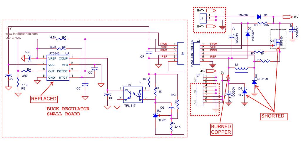 |
||||||
Made corrections to the Opto-driver schematic. I hope I got it right this time. Opto Driver_Bias(Rev2).pdf Edited 2025-09-09 02:57 by tinyt |
||||||
So, I assembled the two identical circuits on two prototyping boards. 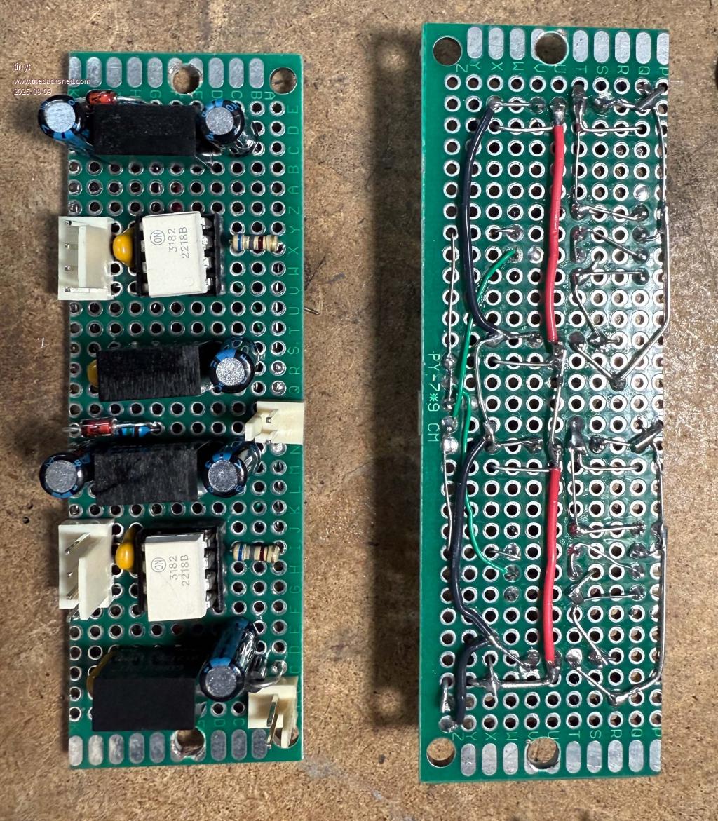 I tested the ouput voltages and they were as expected. With no input, the output of the FOD3182 is at negative bias voltage. I drilled and tapped the top of the heat sinks to mount the boards. 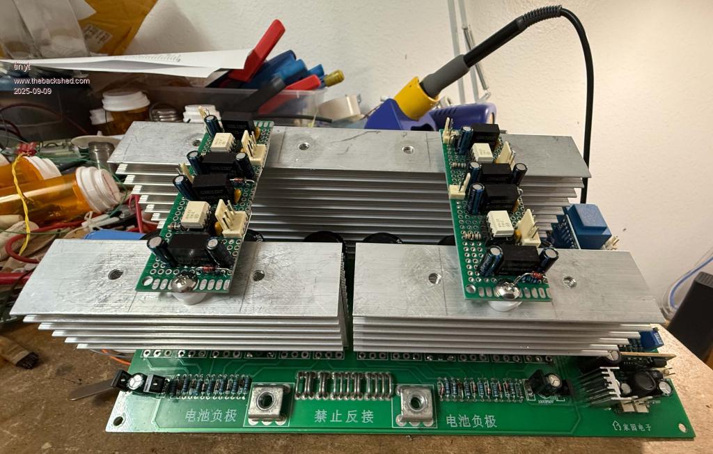 I then looked at my reverse circuit drawing of the inverter. To fit the new driver circuits, I have to make 12 copper trace cuts, solder 2 jumpers, and solder a total of 22 wires for the connector harnesses. And I chickened out.  A lot of things can go wrong: MY reverse is not accurate, mistakes in copper trace cuttings, etc. Also, I have no spare inverter. I have decided to save my work in case I really need to do it in the future. I think for now I will just concentrate on the compressor motor soft-start. And make sure I don't overload the inverter really bad. Edited 2025-09-09 13:20 by tinyt |
||||||
Re the AC compressor. This may be a longshot but it is worth checking that the start capacitor measured capacitance matches the value printed on the side. Long ago I was asked to fix a large air compressor that wouldn't start, just sit and hum till the overload tripped. When he brought it into the workshop it worked perfectly. He had been using it on a long extension lead so we tried that and it wouldn't start. With the high start current the voltage at the end of the lead while starting was only about 10V low, but that was enough. That should not have been a problem so checked the capacitor and it was only one third of the marked value. Cut the can open and found it contained 3 parallel caps, 2 open circuit. A new one solved the problem. So the possibility is that your AC may be ok on full mains volts but not if the inverter sags with the high start current. Regardless of whether that is the problem here the triac starter should still help. |
||||||
Thanks for the tip. The HVAC that blew the inverter is newly installed (about 8 months). Nameplate says 2024. 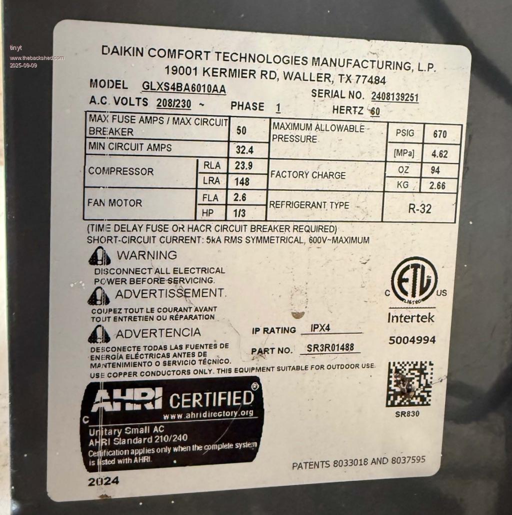 Here are some pages of the spec (schematic included). goodman-glxs4ba6010-specification-some sheets.pdf We have decided not to power it with the inverter, we think it is overkill to power it with our inverter, besides battery capacity is not enough to power it long enough. My other son's A/C is much older, close to 30 years and still running. We have operated this with the inverter several times already with no problem. But, we don't want to stress the mosfets, so we are going to use soft start on this one. 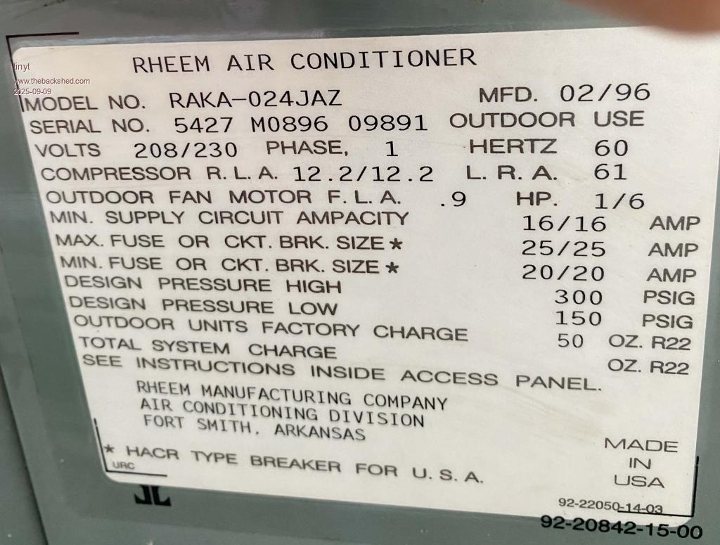 Micro-air is still not affordable, so I ordered these. 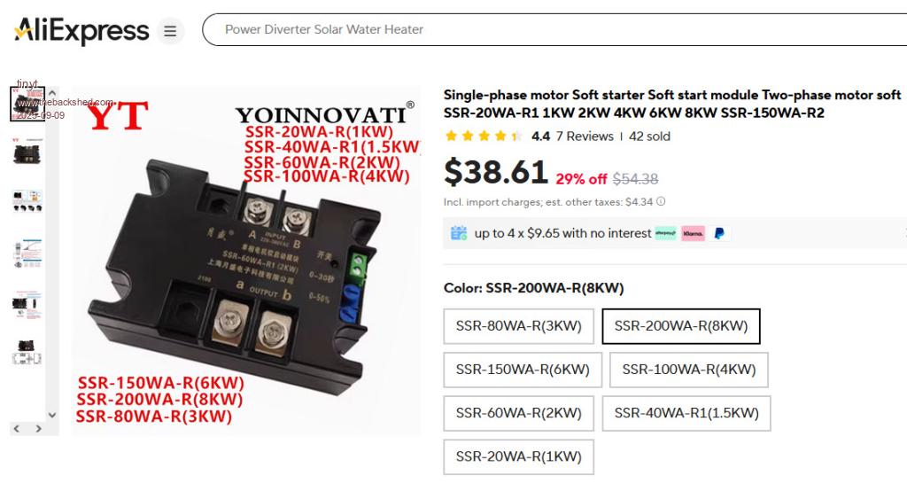 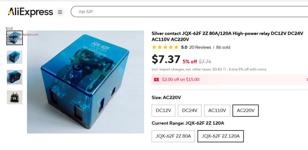 The plan is to set the ramp voltage time of the SSR to about 1/2 second or even less so as not to stall the motor, then with a tbd. delay circuit activate the HD relay to bypass the SSR. This way we don't overheat the SSR. I hope this works. |
||||||
Can't blame you. That's certainly more mods than I expected. |
||||||
Watching some commercial inverter A/C starting test (fail) videos reminded me of this. Would like to better understand how a 5kVA transformer starts a 5 ton A/C (well above the surge capability of most LF inverters). It's still a bit hard to imagine the voltage holding up high and long enough for the surge load. I am wondering what's different about your transformer. Can you share the transformer primary and secondary winding voltages and wire gauges? |
||||||
Complete build including testing results are in this forum. https://diysolarforum.com/threads/another-inverter-build.53006/ |
||||||
Interesting build thread. From a quick scan, it seems the transformer has the following windings: * Primary: 26VAC with 41.6mm2 (~1 AWG) winding. * Secondary: 280VAC (2 x 140VAC) with 7.3mm2 (~8.5 AWG) winding. Do I have correct understanding? If so, the windings seem a bit more beefy than I expected in a 5kVA transformer. Perhaps more important is the 10+ winding ratio which certainly seems higher than most other builds. I suspect these differences helped quite a bit to keep the output voltage high enough to start large inductive loads. It's also remarkable that the transformer only weights 42 lbs. Edited 2025-09-30 05:06 by analog8484 |
||||||
For reference here is the data sheet of the original toroid transformer with my notes in red. 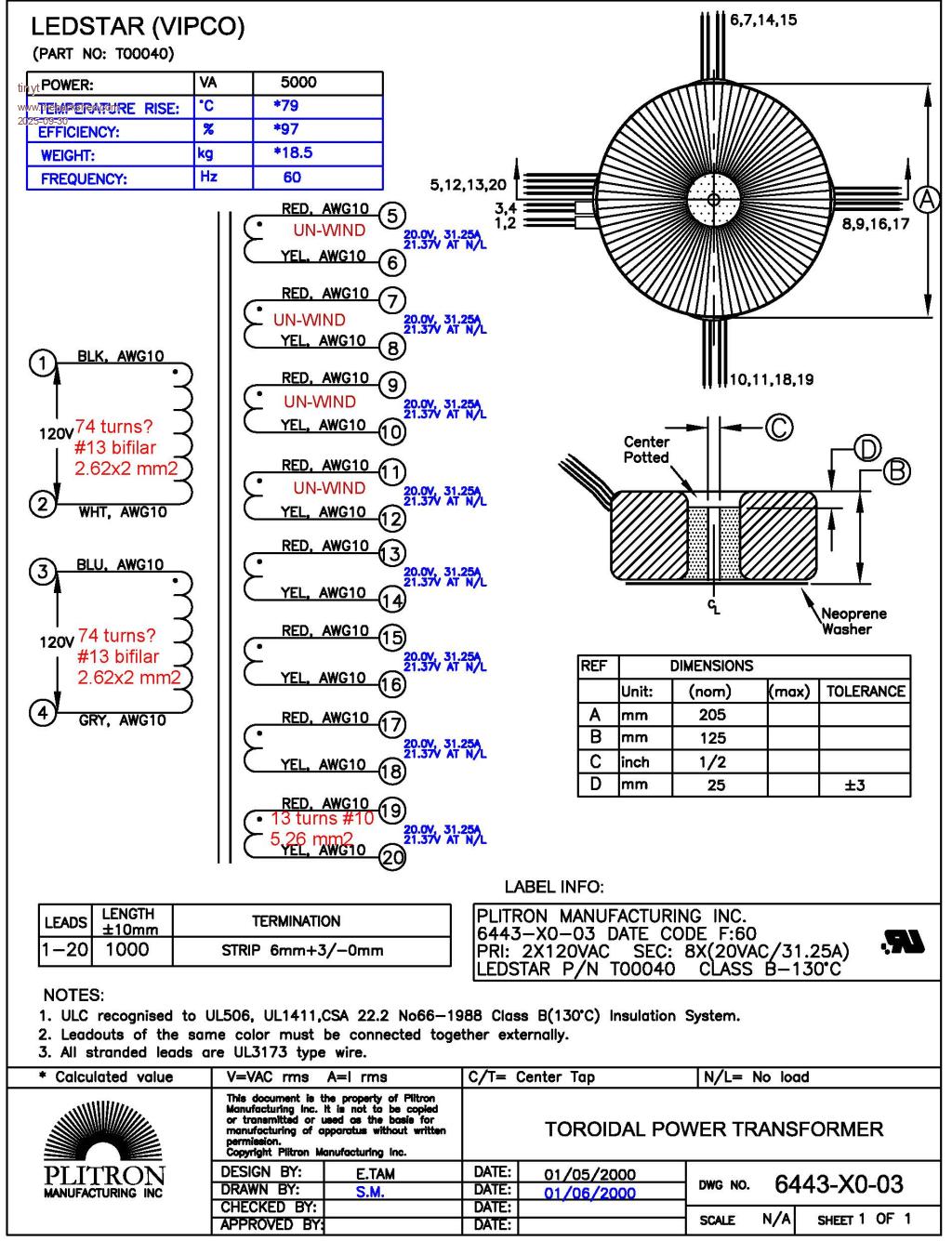 Calculated weight says 18.5 kg (40.78 lbs). Seem that my mod added only 1.3 lbs. Here also shows my modification in stages. 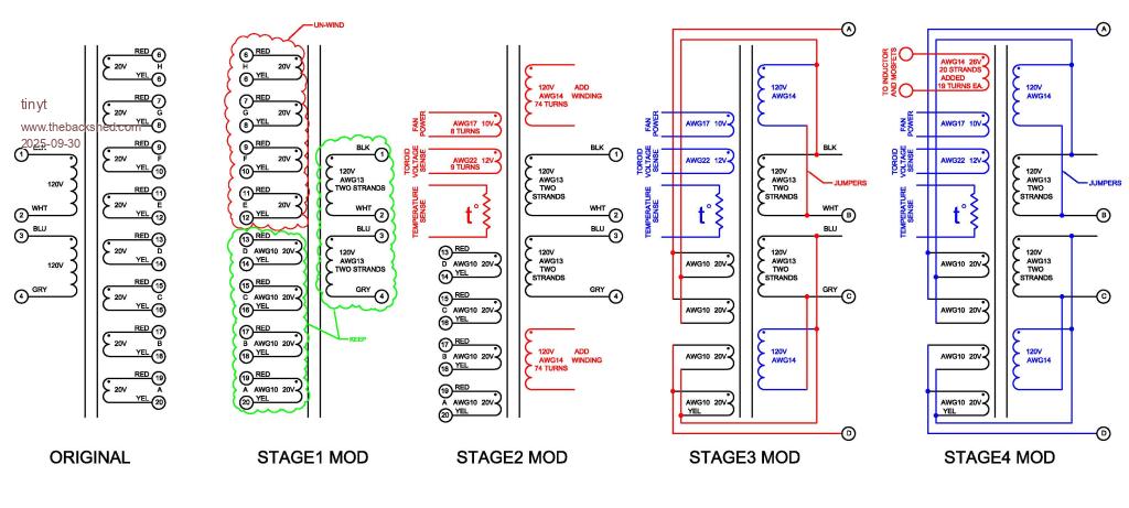 Using my notes and the picture above, and using number of turns instead of voltage, turns ratio is ((74 + 13) x 2) / 19 = 9.15 Secondary cross section for the 74 turns (120V) is (2.624 x 2) = 6.8757 mm2 for the 13 turns (20v) is (1.6277 x 2) = 5.176 mm2 Primary cross section for the 19 turns (26v) is 1.6277 x 20 = 32.55 mm2 I hope I got my rithmetic right. Edited 2025-09-30 07:12 by tinyt |
||||||
AFAIK, the only inverter of similar power rating that can start a 5 ton A/C (without soft start) is the Schneider XW PRO which is rated for 6.8kW and has an 80 lb transformer. It's remarkable that your inverter can start a 5 ton A/C with a transformer that's half the weight. That turns ratio is certainly closer to typical. So, is the actual voltage ratio similar (26VAC to ~238VAC)? If so, it seems the original transformer datasheet voltage ratio was a bit off? Hmm ... the build thread and the diagram above indicate 14 AWG for each strand for the primary winding which has a 2.08 mm2 cross section. The 1.6277 number looks more like the diameter of 14 AWG. For the secondary winding (the 120V portion), the build thread and diagram indicate 2x13AWG + 1x14AWG. The "2.624x2" above would mean only 2x13AWG? Can you verify? In any case, if you ever run the 5 ton A/C again with the inverter, it would be great to know how low the voltage gets. |
||||||
Yes, you are correct, at my age I keep making mistakes now. AWG 14 cross-section is 2.08 mm2. And you are also correct for the secondary: The 120v section is 2x2.624 + 2.08 = 7.328 mm2 And the 20v section is 2x5.267 = 10.534 mm2 The primary is 20x2.08 = 41.6 mm2 |
||||||
So, I used a Fluke 179 and took actual voltage measurements: No load: Secondary(L1-L2) = 236.6vac Primary = 26.16vac Primary including the choke = 31.9 spwm Calculated turns ratio: 236.6/26.16 = 9.044 L1-N loaded with 120vac pool pump drawing 7.6A Secondary(L1-L2) = 237vac Primary = 26.37vac Primary including the choke = 32.5 spwm Calculated turns ratio: 237/26.37 = 8.987 Note that no load voltage output is lower than with load. We noticed this on the 3 inverters that I built. |
||||||
Sounds like you are measuring this in the Inverter, so that's likely a bit of switching noise skewing the VFB sense or slight distortion on the AC VFB from the load ETC, so the load to unload comparison may be a little off. Is spwm = duty cycle spwm % (if accurate) it's extremely low? Very nice build by the way to fit all of that in a relatively compact space. |
||||||
| The Back Shed's forum code is written, and hosted, in Australia. |

