Posted: 05:49am 02 Oct 2025 Copy link to clipboard
phil99 Guru
At about 450µA @ 3.3V it may be too hungry for Grog's application.
Posted: 07:28am 02 Oct 2025 Copy link to clipboard
Mixtel90 Guru
I doubt if a latch would be needed for this application. If the pins were read using PORT it would be extremely unlucky if they changed during the read. Keep it as simple as possible. A 74VHC4040 has a quiescent current of 4uA at 5V and will run at half that voltage.
If possible it would be interesting to force the clock input high (it is active low) for a ms or so before reading. Maybe clock it via a resistor but connect it directly to a MM pin that is switched from DIN to DOUT ON. That way the ripple count of a 74VHC4040 would be stable. . Edited 2025-10-02 17:30 by Mixtel90
Posted: 07:46am 02 Oct 2025 Copy link to clipboard
TassyJim Guru
Not needed. If you are worried, read the port twice a few uS apart and compare the two.
I know I should have a few 4040 ICs somewhere, but having trouble finding them.
Jim
Posted: 07:49am 02 Oct 2025 Copy link to clipboard
Mixtel90 Guru
I'm not sure if the old CD4040 will work down to 3V3. It was designed for at least 5V originally. I must admit, I've not tried one. :)
Posted: 07:53am 02 Oct 2025 Copy link to clipboard
TassyJim Guru
My datasheet says 3V min for the CD4040B I agree that 3V will be at the limit and if there is 5V available, I would use it. At least the micromite has plenty of 5V tolerant pins.
I was surprised that you can still but the DIL version. Jim Edited 2025-10-02 18:04 by TassyJim
Posted: 08:04am 02 Oct 2025 Copy link to clipboard
Mixtel90 Guru
That's fine then. :) I always liked the old CMOS chips. Especially the ones without static protection... :(
Posted: 10:46am 02 Oct 2025 Copy link to clipboard
Volhout Guru
There is also an analog solution
+3V3 ---------LDR-----------10meg-----GND
Put the LDR over the LED Put a 100uF cap parallel to the 10meg resistor Use ADC to measure voltage accross cap
This voltage is linear related to the number of pulses, but only changes slow. Could be minutes to change from one stable value to the other stable value.
About TassyJim's idea. When the number of pins is a problem
Only 2 pins: - counter CLK - Counter Q6
All bits over Q6 are ignored. Generate clock pulses until Q6 goes high (this is in fact a reset of Q0...Q5) Go to sleep
After 5 seconds , wake up. Generate N clock pulses until Q6 goes high. - You have reset the counter for the next run - The original number of pulses from the charger is 2^6 - N
Regards,
Volhout P.S. I have made a cheap RTC in the 1980's using this method with 4040's. Edited 2025-10-02 20:58 by Volhout
Posted: 11:57am 02 Oct 2025 Copy link to clipboard
Mixtel90 Guru
The analogue version is beautifully steam-punk. :)
I like that counter idea. Very neat!
Posted: 07:22pm 02 Oct 2025 Copy link to clipboard
circuit Senior Member
Everybody seems to have forgotten about the VERY low power alternative to the MM2; the Armmite L4. It is a port (by Peter Mather, of course) of MicroMite Basic loaded onto an STM32L43 processor. This can RUN as low as 800uA. And its sleep mode is x12 lower than the MM2 -only 3uA as against the 40uA of the MM2. Would this solve the problem? Edited 2025-10-03 05:25 by circuit
Posted: 07:41pm 02 Oct 2025 Copy link to clipboard
JohnS Guru
Good idea!
John
Posted: 09:31pm 02 Oct 2025 Copy link to clipboard
Mixtel90 Guru
If it's a MM2 project then swapping the chip might not be the most popular idea. :) Would it wake up and count the first pulse in time?
Posted: 11:49pm 02 Oct 2025 Copy link to clipboard
bigmik Guru
Grogs,
Why the need to read the ‘report’ of battery state? Cant you just use an analog input to read the battery voltage directly?
Mick
.
Posted: 01:01am 03 Oct 2025 Copy link to clipboard
phil99 Guru
No! Too sane, sensible, logical and simple. A technician would do it that way but an engineer does it the hard way.
Brings to mind the Oppenheimer movie. Designing the prototype uranium bomb someone suggests to keep it simple by using a cannon barrel and explosives to create the critical mass. Another calculates that the speed would need to be so high it would wear out the barrel. They all spend ages trying to devise complicated ways to overcome this problem till someone asks "How many times are we going to use it?" . Edited 2025-10-03 11:05 by phil99
Posted: 02:14am 03 Oct 2025 Copy link to clipboard
zeitfest Guru
What is tilting, that the tilt sensor is detecting ? Edited 2025-10-03 12:15 by zeitfest
Posted: 08:08am 03 Oct 2025 Copy link to clipboard
Mixtel90 Guru
It's not quite so straightforward using an analogue input and a potential divider. The PD will be a drain on the battery so you need a mosfet or something to isolate the top side. You can't isolate it from GND as that will pull the ADC input up to battery voltage even during sleep.
Posted: 08:18am 03 Oct 2025 Copy link to clipboard
phil99 Guru
The maximum cell volts will be 4.2V so 2 or 3 1N4148 diodes and a 100kΩ in series from the cell to an AIN pin and 1.0MΩ to ⏚ may do the job. A little testing to find what AIN values correspond to the cell volts will be needed.
With the pin set to OFF between reads it should be ok. Current drain of the divider may be less than a CMOS chip. . Edited 2025-10-03 18:31 by phil99
Posted: 09:02am 03 Oct 2025 Copy link to clipboard
ville56 Senior Member
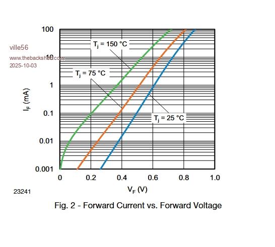
If you look at the datasheet of the 1N4148, I think you will need some more diodes to get the voltage drop you want at this low current and you are a bit dependent on the temperature. So your milage may vary ....
Posted: 09:13am 03 Oct 2025 Copy link to clipboard
Volhout Guru
Maybe use a resistor voltage divider in stead of diodes.
For the lithium cell battery, to determine the charge level from the battery voltage you need to measure very accurate (milivolt accuracy) and even temperature data.
Silicon diodes forward voltage changes 2mV per degree kelvin (Celcius). 3 diodes in series = 6mV/C. You can only measure milivolt accurate on the voltage level when you keep the battery circuit within 0.16 degrees C... Big NONO.
You need a resistor divider.
Volhout
P.S. It can be done with diodes as well, but that requires a lot of engineering where you use and NTC or PTC and a selected set of accurate resistors that change the current through the diodes depending on the temperature. Basically compensating for the 6mV/C by changing the forward voltage. Don't go that way. It has been done by companies like HP where they needed to compensate of forward voltage drop in an old RF detector probe. Too much hassle. Edited 2025-10-03 19:14 by Volhout
Posted: 09:36am 03 Oct 2025 Copy link to clipboard
Mixtel90 Guru
A silicon diode is a great way to measure temperature because the Vf-temperature slope has quite a good repeat accuracy over a sensible range. So, never use them where temperature change may be an issue. :)
I don't like measuring the voltage of a lithium cell to determine it's remaining capacity. It tells lies. You really need to log the charge into the cell and the load current from it. Without doing that anything else is pretty much a guess. The capacity varies with temperature and load current. Also, the difference in terminal voltage between half remaining and unusable is very small as you are very close to the knee point of the discharge curve.
Posted: 11:45am 03 Oct 2025 Copy link to clipboard
phil99 Guru
A proper charge monitor would run on a couple of µA?
The alternative is to go back to the 4 level flashing LED of the charge/boost chip. Its thresholds are not shown in the data sheet. Temperature compensation isn't mentioned at all and it won't be integrating charge/discharge current.
Just 4 points from empty to full is no better than an inaccurate voltage divider. All that is needed is to indicate when the cell needs recharging. Just a single point a little above flat. The LED can be removed to save a few µA.
From the data sheet. Charge Termination - Voltage 4.15min 4.2typ 4.24max V Recharge Threshold - 4.05typ V (min, max not given) Trickle Charge Voltage threshold - 2.65min 2.87typ 3.1max V
Nothing given for the LED levels. Perhaps level 1 = Trickle Charge Voltage threshold - 2.65min 2.87typ 3.1max V and level 4 = Charge Termination - Voltage 4.15min 4.2typ 4.24max V but just guessing. If this is the case the lowest threshold is quite vague - 2.65 to 3.1 V
Page 2 of 3
The Back Shed's forum code is written, and hosted, in Australia.