Here is what I have done.
I use a test inverter that does not have huge DC bus capacitance
which reduces the risk of destruction. Capacitance is 6,600 uF.
Test inverter uses a 1.5kW toroid and primary winding voltage
is only 21V AC RMS for the 54V DC supply.
When running PWM width is only about 460 clocks of the
795 clock width maximum when outputting 240V AC.
I doubt the above is critical to the performance of the DC imbalance scheme.
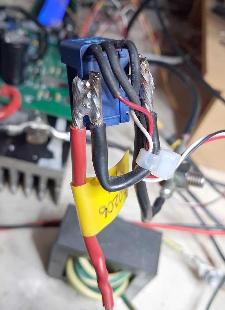
Only one extra component is needed. A modified LEM CASR 15-NP
current sensor. It has 4 pins, 5V, GND, OUT and REL
I leave REL unconnected. OUT is at 2.5V with zero current passing through the sense wires.
I modify the sensor as seen below, to decrease it's sensitivity
by putting a shunt on the current sense wires.
It is now 0.0206V/Amp
I connect the sensor to the Nano's 5V,GND and A7 pins.
The control scheme:
In this discussion I will call the two outputs from the inverter board
V1 and V2. We know that we create the AC voltage on the primary winding
by alternatively driving V1 from zero to AC peak voltage and back to zero
while holding V2 to DC ground.
And then we drive V2 from zero to AC peak and back to zero while holding V1 to DC ground.
This is how we synthesize the AC waveform.
In my code I maintain a variable that is = 1 when V1 is active
It is = 0 when V2 is active. We need this for the control scheme.
When the AC voltage crosses zero, I obtain the primary current from the sensor and store
it in either "pc_v1" if V1 is active or store it in "pc_v2" is V2 is active.
if (v1_active == 1)
pc_v1 = fabs((float)(analogRead(PRI_SENSE) - 514)) ; // need only absolute value of current at zero crossing
else // but must check both times
pc_v2 = fabs((float)(analogRead(PRI_SENSE) - 514)) ; // and store the two values
This way I can get information on which output is driving the toroid to saturation.
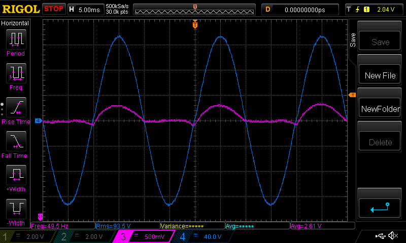
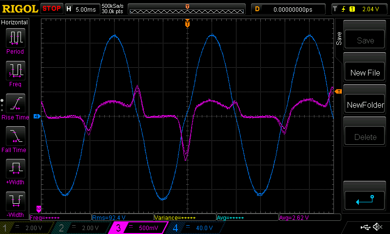
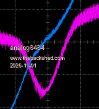
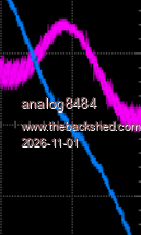
I noticed that the high current from saturation is present at zero crossing and it
occurs after the corresponding 1/2 wave was driven by the inverter.
If V1 was active, then I saw a large pc_v1 value relative to pc_v2 and if
V2 is active, I saw a large pc_v2 relative to pc_v1
I only store the absolute values so current sensor orientation is not important!
(Should the load not be purely resistive there will be a phase delay or lead in the
primary current. Let's say it's leading and so I expect (with zero evidence to support
myself) that the Voltage zero crossing instants will have currents that are similar in
magnitude but opposite signs. if all is well, no DC imbalance such that the toroid
will saturate. I think my scheme will work with reactive loading of significant
percentages too. I can't test this, I need a small AC motor or something.)
I then run one of two closed loop controls which provide for changing the main output variable
called "i_balance". This variable can move between strict limits, in my case of from
-0.1 to +0.1 This is more than enough for testing with loads up to 400W with or without the diode
in series.
The simple closed loop control is "bang-bang" and is easy to work out.
if (pc_v1 > pc_v2) i_balance -= 0.001;
if (pc_v1 < pc_v2) i_balance += 0.001;
what it means is i_balance will slowly move more negative if the current when V1 is active
is larger than the current when V2 is active.
And conversely, i_balance will move more positive if V2 current is greater than V1.
I then check if i_balance is within safe limits (+/- 0.1) and then modify the
corresponding inverter output voltage to suit.
if (i_balance > 0.0)
{
vpwr_v2 = (int)((float)PPWM * pwr);
vpwr_v1 = (int)((float)PPWM * pwr * (1.0 - i_balance));
}
else
{
vpwr_v1 = (int)((float)PPWM * pwr);
vpwr_v2 = (int)((float)PPWM * pwr * (1.0 + i_balance));
}
what this does is it combines both the DC balance control and the AC output voltage control
in one statement.
Firstly, notice I calculate pwm amplitude maximum values for the 2 half waves
and not simply calculate a single value used for both V1 and V2 as in ALL PAST FIRMWARE.
if i_balance is > 0 i.e. positive, it means V1 was getting into saturation and so we
need to reduce it's amplitude. This is done by multiplying the amplitude by (1.0 - i_balance)
which will be something smaller than 1.0 and so it will reduce the amplitude.
Which is what we need.
if i_balance < 0 i.e. negative that means V2 is getting into saturation to some degree
and so we need to reduce V2 amplitude. Since i_balance is negative I use
(1.0 + i_balance) as the expression.
That is all bang-bang control is, pretty simple to do. It does not even need to know
the actual values of the two current measurements, it only needs to know
which one is larger than the other.
Of course we need some changes in the interrupt code to use the now 2 seperate
max. pwm values for V1 and V2 output. It looks like this now.
if (v1_active == 1)
{
c = (l[pcount] * vpwr_v1) >> 16;
OCR1B = c;
}
else
{
c = (l[pcount] * vpwr_v2) >> 16;
OCR1A = c;
}
This way I can modify one or the other 1/2 wave output voltage independently from the other
which is needed for this scheme to work.
I implement a soft start for the DC balance control, for the first 2.5 seconds
I let the bang-bang control bring things back to near DC current balance at zero crossings
then I switch over to PID.
We now use the values of the current measurements to calculate correction factor to
add to i_balance.
once bang-bang is complete, I now run this code instead of the b-b code:
Setpoint[1] = 0.0;
Input[1] = pc_v1 - pc_v2; // where the magic happens.
do_pid(1);
i_balance = i_balance + Output[1];
I define the desired setpoint, we want zero imbalance of the two zero crossing current values
I feed the PID control what is happening, which is pc_v1 - pc_v2, i.e. the AC current imbalance
then I run the PID code and get the result which is added to i_balance
and then the same limit testing of i_blance before I modify the required 1/2 wave
amplitude as seen above.
Because I now need 2 PID controls, I modified the code to work with 2 sets of values for
the two control loops, one being the AC output voltage and the other the new DC balance loop.
From trial and error, I found I need rather small values of P and D for the DC balance loop.
This is likely due to my code using A-D converter counts as the working values in
the variables pc_v1 and pc_v2. Roughly there are 4 counts per Amp when the sensor output is
converted.
Edited 2026-10-25 19:00 by poida



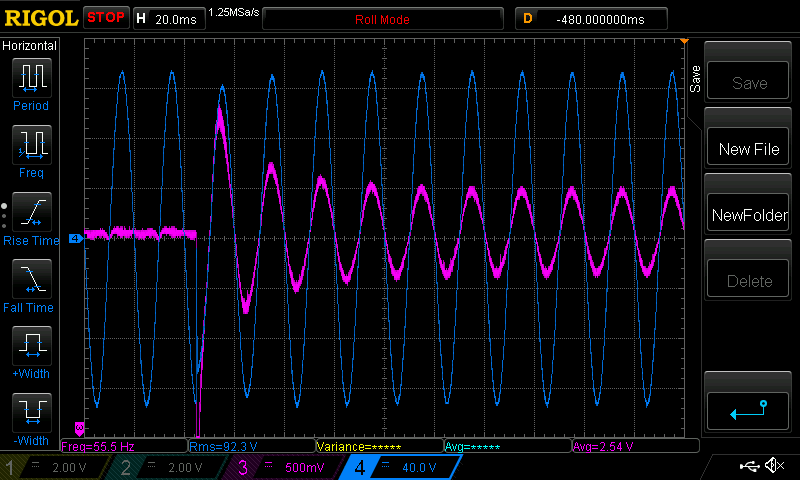
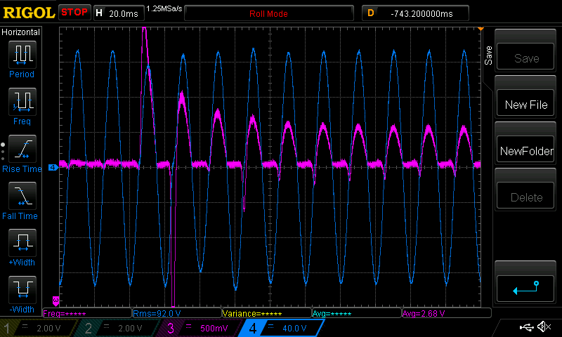
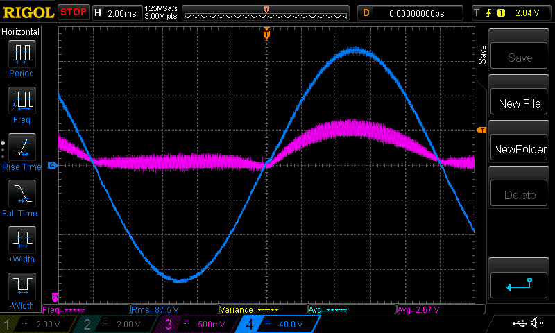
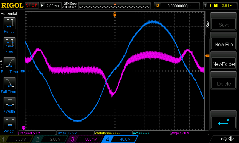
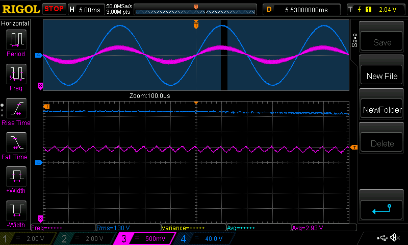
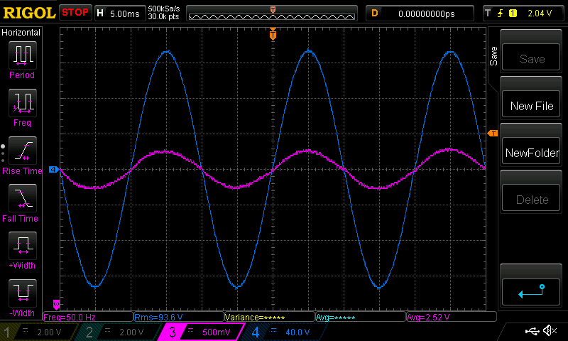
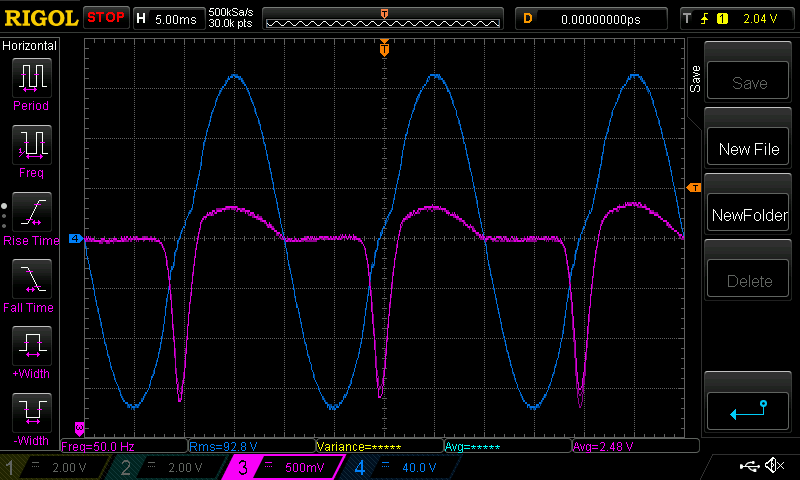



 however the inverter would shut down due to over voltage on the DC bus.