Posted: 12:11am 21 Sep 2025 Copy link to clipboard
Bryan1 Guru
G'Day Guy's, Well made an early start and finally got the first of the windings off, so setup my spool winder I made back in the '90's and it worked a treat getting the kinks out of the 1.8mm wire
Now our young cat thought moving wire was a toy so it was pouncing on the wire and trying to bite it so grabbed it by the scruff of the neck and took it back inside as the last thing I need is damaged enamel caused by the cat munching on it.
Anyway the weight of the first winding is .75 Kg so I should be able to fit the whole winding on my spool.
Regards Bryan
Posted: 12:17am 21 Sep 2025 Copy link to clipboard
wiseguy Guru
Maybe I missed something in the procedure but why not leave the extra 10 turns (or whatever number is discovered from the temporary 10 turns to determine the final secondary voltage required) from the outer winding instead of a complete strip and then only the one termination of the 3 copper wires is needed without having to add the turns again. Phasing the “new” 10? turns so it adds correctly to the inner winding is still required? Good luck with the new toroid wind. Edited 2025-09-21 10:24 by wiseguy
Posted: 07:27am 21 Sep 2025 Copy link to clipboard
Bryan1 Guru
Hi Mike as this is my first array into modifying toroids that guide from the member Cobbler has been a great to me in PM so I am glad to be able put his great info onto the forum for everyone to read.
Now for me with 24 volts 36sqmm cable would be the best for the primary and trying to get thru the hole on a unmodified toroid just wont happen.
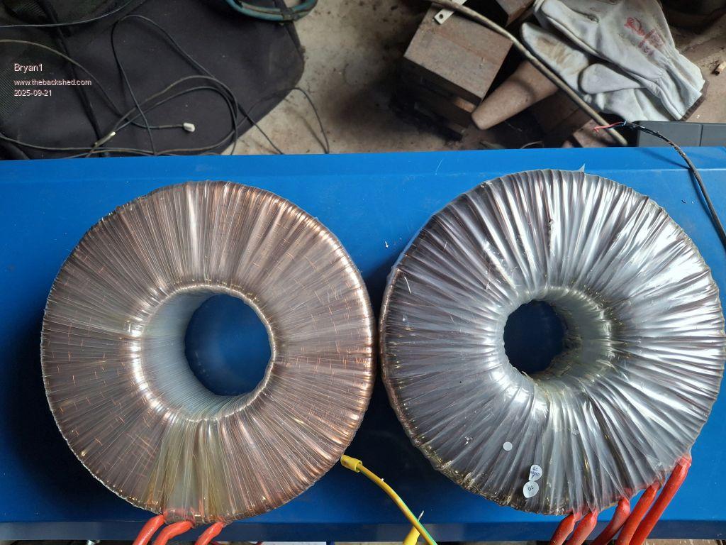
Now here is a picture comparing the 2
Now this toroid I was working on did have a 4th winding installed that wasn't used and 1/2 way taking it out the toroid hit the deck and scratched a heap of the wire so what was left got cut off and into my copper scrap bin.
Now in the guide I reckon I will add 16 turns to start, get a voltage reading then take a turn off and measure again to get volts per turn so the primary turns can be worked out accurately.
Now on taking out the 250 volt winding it was wound clockwise so I do think it's safe to assume the primary will be the same. Also the total 1.8mm spool weight came in at 2.35Kg so plenty to play with later.
Regards Bryan Edited 2025-09-21 17:50 by Bryan1
Posted: 12:06am 22 Sep 2025 Copy link to clipboard
Godoh Guru
Hi Bryan, good luck with the windings. It seems that the Aerosharps are good transformers for this project. Being able to keep the original high voltage windings is a boon. For my inverters some of the high voltage windings were aluminium so they just came off and went into the scrap bin. I did both my inverters the same, fully unwound, glued the cores together, (after taking some of the centre laminations out) and rewound them. It is a job to wind a couple of hundred turns on but still not bad with a big hoop. great to see the project proceeding Pete
Posted: 12:48am 22 Sep 2025 Copy link to clipboard
wiseguy Guru
Hi Brian, just want to clarify my previous post. The outer winding must be removed almost fully but leaving the number of turns (10 or so) instead of having to add them back to the toroid after a complete removal. Maybe you understood that but it was not clear from your reply. Great input & guide from Cobbler !
Posted: 07:46am 22 Sep 2025 Copy link to clipboard
Bryan1 Guru
Hi Mike the dummy winding was the first winding so leaving turns on wasn't possible, now to clarify when I said the windings were clockwise this was with the output wires to the rear so off that I would say the white output wire on the primary is the end of the winding so that is the one to take off so the new 3 inhand windings say 16 turns or a couple more so I can take a turn off after measuring the voltage and idle current which will let me know the volts/turn number so I can get the new primary turns correct.
Now I will wait until my statement above is correct as there is no rush with this as I want to get this right first time.
Regards Bryan
Posted: 09:13am 24 Sep 2025 Copy link to clipboard
Bryan1 Guru
Anyway to proceed with this project just talked with Roger and this Saturday myself and the toroid is going to his place as putting 240 volts AC across this toroid does have a scare factor to me.
So I think it is best to get a second hand that knows AC so I can learn as we we go
Regards Bryan
Posted: 07:53am 27 Sep 2025 Copy link to clipboard
rogerdw Guru
Hi guys. Well Bryan and I made a start on his toroid ... and after having read all the notes and thinking I knew what to do ... I've ended up unsure of what we've got and if I made a mistake somewhere.
We started with just the 230V primary winding, though still covered by the grounding tape. We wound on 10 turns of wire, then applied 230V using a variac to be exact.
There was 12.85V across the 10 turns ... so 1.285V/Turn
Bryan has an AC mA meter, so we measured 75mA @ 230V. Equals 17.25watts idle power.
We wanted to aim for 250V for the primary, so need to add 20V.
Of course by now I was second guessing everything ... so have to confess my ignorance and see what the experts can tell us. Please.
Posted: 07:59am 27 Sep 2025 Copy link to clipboard
disco4now Guru
Any chance the extra turns are connected in the reverse direction, so actually subtracting.
Posted: 08:12am 27 Sep 2025 Copy link to clipboard
rogerdw Guru
Thanks ... I did consider that ... but we are getting a higher volts/turn reading than before ... plus I used the dso to check the winding phase before we connected it up. Hmmm.
Posted: 08:26am 27 Sep 2025 Copy link to clipboard
Bryan1 Guru
Well many thanks to Roger for helping me out today which was a great learning experience
Well after setting up my Aneng DMM on AC mA current measurement I did say I was prone to try and measure voltage while in current mode. Now my DMM was showing a different AC voltage to Rogers trusty Fluke DMM so we decided to test the 240 volt AC and sure enough what I said earlier happened didn't it Blew the 10 amp ceramic fuse and left a nice black mark on the power point along with setting off the circuit breaker.
Now seeing how the loop method of winding toroids looked so simple the tips given were golden and I think I learned enough for in the future when I do the next toroid I can do it myself.
Off the information Michael had given me and further research to learn the fact the idle current went up and not down had both of us beat.
So Yes if the experts can help us out on why the idle current went up and not down it would be great to learn.
Now I did suggest today what if we setup a 240 volt/15 volt transformer with 16 turns and just run the toroid and the suggestion was how about we just use the variac but we didn't get that far as it was getting late in the day the issue with the idle power consumed the time.
Now Roger if you are free tomorrow do you want to try this option as it may provide a different result where testing out the toroid in real life conditions may just prove different figures and I have to be there to see.
Regards Bryan Edited 2025-09-27 18:36 by Bryan1
Posted: 08:52am 27 Sep 2025 Copy link to clipboard
phil99 Guru
Disco4now is almost certainly correct. Reverse the connections of the extra turns and measure again.
A better check would be to measure the voltage across the combined 230V + 20V windings (250V if you set the Variac to that). Then measure the 230V winding. If you read 230V you have it the right way around, if reversed you will get 270V and thus higher current.
That will be 17.25 Volt-Amps not Watts. An unloaded transformer is an inductor and those big toroids are very efficient so the power factor might be around 0.1 so the actual power loss may be as little as 2 Watts.
Posted: 09:18am 27 Sep 2025 Copy link to clipboard
Bryan1 Guru
Well it does look like I will have to bring my gloves up tomorrow so I can rewind the toroid the other way and Roger can hold the hoop this time.
Now think on Roger on what I said about that 250 volt winding and we did go the other way so what Phil and Disco has said does ring true.
The only thing is tomorrow we will go out to lunch and I pay as it can be my way of saying Thanks for all you have done for me.
There will be enough 1.8mm wire on the spool before the join so looks like we have to start again and just to a second join on the wire so we can wind the other way.
About 10am again mate ?
Cheers Bryan Edited 2025-09-27 19:26 by Bryan1
Posted: 09:39am 27 Sep 2025 Copy link to clipboard
Bryan1 Guru
Now Phil if my suggestion of putting 16 turns and using the variac then running the toroid to do a measurement first just to see how it goes then take the measurements to see what the real conditions are.
Now I am totally green in this whole subject but I am learning and having Roger there to help does go along way
Now off my learning if we did go the wrong way why didn't the voltage substrat it was going the wrong way as it should or as we are seeing a higher idle current the cause. Edited 2025-09-27 19:52 by Bryan1
Posted: 09:58am 27 Sep 2025 Copy link to clipboard
phil99 Guru
You don't need to do that. Just swapping the ends of the extra winding will achieve the same result. In one direction the voltages add, in the other they subtract.
It may be easier to see it if you have the neutral connected to one end of the 230V winding and the active to the other end of it. With one end of the 20V winding connected to the active measure the voltage from the neutral to the free end of the 20V winding. If the voltage is 20V greater than the supply to the 230V winding then it is correct. If the voltage is 20V less than the supply to the 230V winding then it is reversed.
Swap the ends of the 20V winding and try again. This time it will be 20V greater than the supply.
Posted: 10:43am 27 Sep 2025 Copy link to clipboard
rogerdw Guru
Well I'm a dickhead aren't I ... you guys were right, it was wound the wrong way.
Gonna take me a while to work out why the checks I made still mislead me.
Anyway, I did as you suggested Phil and put 250 across (what I thought was) the full winding ... and the join at the end of the original was 265 ... so no doubt about that.
I unsoldered the 3 joins and roughly hooked just one winding in the opposite direction ... tried it again ... and clearly the correct way now. 250 across the lot and the tapping ~240V (only 12T at present).
My clamp meter is only 600 or 1000 amps, so not accurate on low current like Bryan's, but it looked like around around 90mA.
So thanks very much disco4now and Phil, we're back on track ... I hope.
A couple questions ...
The numbers we got pointed towards 15 or 16 turns extra needed to suit 250V. What takes priority once they are wound ... a change in idle current up or down ... or just add the 16 and leave it alone?
Cobbler suggested seperating the 3 original ends that were joined and connecting a wire to each and keeping them insulated ... then common them at the end. Is that totally necessary ... could we have just joined the 3 wires to the previous end and then just carried on with the extra 16T?
Yes, Bryan we can have another go tomorrow ... and 10's ok. We could just leave the windings and swap the ends ... but it will be tidier to redo them. I don't think there's any reason why we can't just re-use the wire that's on there. At least they are all the correct length now.
Posted: 10:53am 27 Sep 2025 Copy link to clipboard
phil99 Guru
Yes, As long as the number of turns of the 3 new wires are the same and lengths roughly the same it makes no difference.
Posted: 11:50am 27 Sep 2025 Copy link to clipboard
wiseguy Guru
One of the problems which will have you chasing your tail is that the idle current is not proportional to the actual idle power. You need a true power meter to check the idle power as there is a phase difference between the inductive current and the applied ac voltage. I can recommend the Power-Mate Lite for accurate energy measurement. It takes 4800 samples of voltage and current per second and multiplies them, integrating the result as true power. If you multiply rms volts by rms amps you just get apparent power which will always be much higher than the true power. Hope this makes sense - the red wine is currently delicious Jacob’s Creek double barrel Shiraz hic🍷 Edited 2025-09-27 21:52 by wiseguy
Posted: 12:07pm 27 Sep 2025 Copy link to clipboard
wiseguy Guru
BTW the first post on this topic shows the 197/215 turns for the 230/250v windings so when I did the tests I got 18 turns so 16/18 turns ( both close enough) was already worked out and confirmed by Roger.
Posted: 12:49pm 27 Sep 2025 Copy link to clipboard
phil99 Guru
A very nice drop! If your scope has 2 channels you can calculate the true idle power.
P = Vrms x Irms x Cos⌀ where ⌀ is the phase difference between V and I.
For 50Hz 1 cycle (360°) = 20mS so measure the time T between zero crossings for the V and I traces then:-
⌀° = T * 360 / 20 = T mS * 18
I would expect ⌀ to be around 85° so Cos⌀ (power factor) about 0.1
Page 7 of 25
The Back Shed's forum code is written, and hosted, in Australia.


 Blew the 10 amp ceramic fuse and left a nice black mark on the power point along with setting off the circuit breaker.
 ... you guys were right, it was wound the wrong way.