Posted: 11:54pm 27 Sep 2025 Copy link to clipboard
wiseguy Guru
Roger, from (fading?) memory I reckon the idling power was between 10 & 13 watts of true power on the 250V windings (with 240V applied). That should give you a ball park figure to work towards. Edited 2025-09-28 09:55 by wiseguy
Posted: 04:36am 28 Sep 2025 Copy link to clipboard
Bryan1 Guru
G'Day Guy's, This morning we reversed the connection on the 16 turn winding and ran the same tests. Roger had setup a power meter so we could get the true idle watts and man were we surprised on average 10 watts idle power
We did some tests with more turns for very little gain so stayed with the 16 turns and Roger said he will post the test figures later today which will show that little gain.
I used that Dow Corning yellow tape to isolate the winding and Roger did a search for this tape where the price was over $50 a roll So I am glad I did save that box of the tape.
So now one step closer
Cheers Bryan Edited 2025-09-28 14:40 by Bryan1
Posted: 08:54am 28 Sep 2025 Copy link to clipboard
wiseguy Guru
It’s ok Brian happy to help.
Posted: 12:31pm 28 Sep 2025 Copy link to clipboard
rogerdw Guru
Thanks Mike, I wasn't sure what was the most important aspect to focus on, other than getting the winding direction correct.
I know it's not the same as the power meter you suggested but it reminded me I have a digital wattmeter, so I figured I'd try that to see how much difference between turns. It actually showed 10.9 watts at 240V with the extra 16 turns, so your memory is still pretty good. Must be that Jacob’s Creek double barrel Shiraz.
I have enough trouble remembering details about the Warpverter toroids and cores, so these Ozinverter formulae leave me floundering even more. I need hours of reading and refreshing my memory to get anywhere. Should have read this whole thread again first.
It all came together well in the end. We just used the other end of the windings, which had gone most of the way around anyway and were quite close to the originals.
So thanks again Mike, Phil and disco4now.
Posted: 07:19am 29 Sep 2025 Copy link to clipboard
Bryan1 Guru
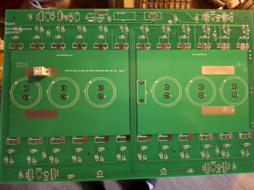
G'Day Guy's, Well I'm now onto the next stage and after spending hours searching this forum I wasn't able to find any pictures of this board at all
Here is a pic of a blank board with one of my 4mm connectors where I bent the legs 90 degrees so they sit on the pads nicely. Now once I do get the cable tightened on the post I reckon soldering it will ensure a solid connection.
Now we have 2 pads on VS1 and VS2 so is only one pad on each needed or both ?
I did a trial fit in one of the aerosharp box's and they are too small for this board so I will drag out that rack mount case from the corner of my shed and use that.
Regards Bryan
Posted: 08:52am 29 Sep 2025 Copy link to clipboard
Revlac Guru
Toroid looks good Bryan, If you were going to use a lot of power, probably use both pads, Think one pad will handle a fair bit anyway, be good to check if you have enough Clarence between that 4mm standoff connector and the heat sink, I have a narrow heatsink, just checked, I could almost get access to that terminal screw after the heatsink is on, with a thicker heatsink there will be no access to the terminal to attach a cable. There is a few other ideas to approach this, I will see if anyone has some more input later.
Posted: 09:02am 29 Sep 2025 Copy link to clipboard
Bryan1 Guru
Thanks for that input Aaron now I do have a heap of 16sqmm cable here so yea using both pads and 2 16sqmm cables going into one connector to the dual choke like I did with that first inverter.
I do have to get a roll of heatsink to fit that thick copper I pulled off that huge transformer from that battery charger as I annealed it on my crab burner.
Out of the 2 aerosharps I only got one big choke so atleast got one to use and this time I will go with 8 turns each side so the inductance is a tad lower.
Posted: 03:47am 04 Oct 2025 Copy link to clipboard
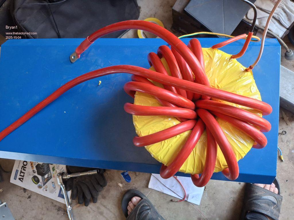
Bryan1 Guru
G'Day Guy's, well went to the 12 volt shop this morning and got 6 metres of 65sqmm red cable and just managed to get 15 turns thru which should be enough and I was told the 65sqmm wire was good for just under 300 amps
Next week I will get a roll of heatshrink so I can insulated that 6.2x4 copper wire so I can make the choke.
also got a bit of work to do on that rack case so getting there.
Regards Bryan
Posted: 05:57am 04 Oct 2025 Copy link to clipboard
Godoh Guru
Looks like it is coming along fine. That is a squeeze fitting in the low voltage winding but it is there, so that is all that counts. Pete
Posted: 06:11am 04 Oct 2025 Copy link to clipboard
Bryan1 Guru
Yes Pete is was fun getting that last turn through and I didn't have enough for another turn either as that 6 metre figure I quoted was just right for 15 turns but at $25 a metre no wastage so I'm pretty happy. got them to put one terminal on the cable and after the trial fit I may go back with the toroid to get the other end crimped as they do a nice job.
Posted: 08:07am 04 Oct 2025 Copy link to clipboard
Godoh Guru
Hi Bryan the exorbitant cost of big battery cable is probably why manufacturers just use multiple strands of magnet wire for the low voltage windings. Also without the thick pvc insulation the magnet wire dumps heat better. $25 a metre is a lot, lucky you didn't need much. good luck with the rest of the build. if you lived close i could crimp the lugs for you, I have a 16 tonne crimper that can crimp up to 350 mm squared cable. I used to borrow a crimper from a wholesaler I dealt with when I was doing electrical work but it worked out so cheap to buy one that i just got my own. have fun Pete
Posted: 08:15am 04 Oct 2025 Copy link to clipboard
mab1 Senior Member
Just thinking that 14 turns might be closer to what's needed for 24v?
But at least you know 14T will fit: a lot easier than trying to get an extra turn in
Glad to see it coming along ( I must get back to my transformer wind sometime...)
Posted: 11:16pm 04 Oct 2025 Copy link to clipboard
Bryan1 Guru
Well my next step is the choke and I am on thinking that 6.5x4 copper wire won't be heavy enough so would going the small stacked toroid that Keepis did be the best solution?
Also I do need to get some more heavy cable for the PCB outlet wire to the choke so would 35sqmm be suitable.
Posted: 11:40pm 04 Oct 2025 Copy link to clipboard
KeepIS Guru
A stacked toroid ring choke is the best way to make a high current choke that also has a higher saturation level.
Yes, 35mm (2G) cable, rated at around 190A to 200A "continuous" duty cycle is ideal.
The small resistance in the choke acts as a buffer to protect the FETS when the S#%t hit the fan, the cokes run cool in normal operation.
When I wound the last chokes, I left enough cable on the choke to fit a crimp connector and reach the PCB output terminal. _ Edited 2025-10-05 09:42 by KeepIS
Posted: 12:31am 05 Oct 2025 Copy link to clipboard
Bryan1 Guru
Hi Keepis I just had a look thru your build looking for the choke data but didn't see what sized wire you used.
Now just thinking out loud here and with that small toroid I got off that old variac lets say I wind several turns of say 50sqmm and do it twice to make a dual toroid how would that go?
With this box I'm going to use there is plenty of room and honestly never seen a choke made this way. The toroid is 170mm diameter with a 85mm hole and 75mm thick.
Edit: Now using 15sqmm wire with 4 turns I get 0.035mH and going more turns does increase the mH so lets say if I used 35sqmm cable I could possibly go 2 inhand on each leg Edited 2025-10-05 10:46 by Bryan1
Posted: 01:22am 05 Oct 2025 Copy link to clipboard
KeepIS Guru
AC Mains Toroids won't work, you need Sendust powder cores.
Something like: Model:MS226060-2 Outer diameter:57.1 mm Inner diameter:26.4 mm Height:15.2 mm Magnetic conductivity:60µ Inductance coefficient:138 nH/N2 Material:85% iron +6% aluminum+9% silicon
These Blue ring toroids were used in chokes in a lot of the older Grid-tie Inverters that used large Toroid transformer AC output.
Ideally 6 of these stacked, with 5 turns of 35mm2, normally you need two chokes to get a total inductance of around 43uH.
A smaller inverter might get away with ONE 8 core stack and 6 turns, but be mindful of surge currents.
I mentioned the wire size in the previous post, a quality 32mm2 cable, or Welding cable.
I used a cable rated at 188A continuous. The Weld Flex cable is rated at 220A but is a bit thicker and did not feel as flexible in cold weather.
Spec I used.
2 B&S (35mm2) 188 amp Copper Cable Single Core Australian Made Nom Area: 32.07mm2 Rated to 188 amps Continuous Use Applications: Battery and Starter Cable, Inverter, Dc-Dc Systems Conductor: OXYGEN FREE Plain Copper Wire to AS/NZS 1125 Insulation: V90 PVC to AS/NZS 3808 Australian Made UV Stable 5V90 PVC Cable. _ Edited 2025-10-05 11:30 by KeepIS
Posted: 01:33am 05 Oct 2025 Copy link to clipboard
Bryan1 Guru
Thanks for that Keepis just placed an order with Ali for 4 sets the 57mm ones too
Now with that 35sqmm cable what was the rough length mate as I have found the cable isn't cheap and with those send dust cores I payed using afterpay and as I had to pay shipping they did say 11-16 Oct Edited 2025-10-05 11:43 by Bryan1
Posted: 02:22am 05 Oct 2025 Copy link to clipboard
KeepIS Guru
Yes, it's a dam shame that the chokes cost a bit to make, but they are critical to the reliability and performance of the inverter.
I will have to look and see if I recorded the length, I have some cores so I'll do quick wind with smaller cable which should get you in the ballpark lenght.
It's worth shopping around for the cable, I know the prices for copper has been going nuts for the past few years and getting worse.
I'll have to check my local guy (works from home) just to see what his prices are.
Posted: 03:42am 05 Oct 2025 Copy link to clipboard
Bryan1 Guru
Yea on Tuesday I will go into M&M the local electrical wholesaler and get a price and also compare that with the 12 volt shop prices, one good thing about the 12 volt shop they always give me a discount as I have used them for donkeys years Also they do a great job crimping the connections for me too.
I also need to source a 175amp Anderson connector and cable for the battery input as that is what I use for the battery connections.
Now this box I'm using is pretty big and I'm thinking of putting the 5Kw Goodwe grid tie inverter on the outside of the box as when I do need to use a heap of power may aswell use the grid tie to supply plenty of power
Gotta go and tame the jungle and later I will get that said box out of the corner of my shed so I can start and plan the layout etc.
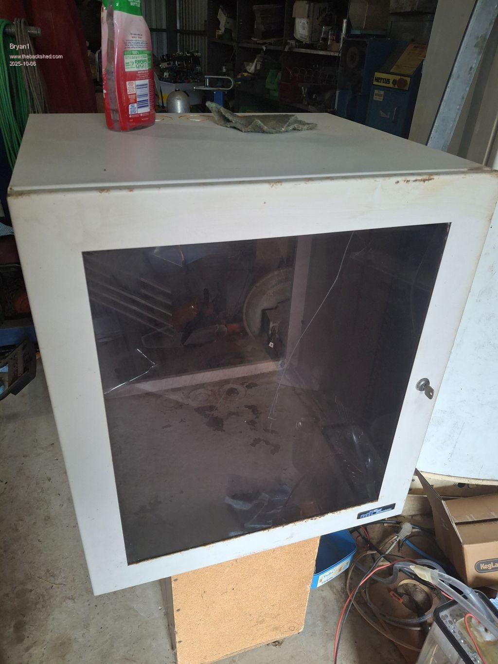
Posted: 12:11am 06 Oct 2025 Copy link to clipboard
Bryan1 Guru
Morning Guy's well had a bit of cleanup and got that rack case out it measures 535x600x450mm so plenty of room to fit everything. This case has sat in the corner for over 20 years and has finally found a use.
Still need to close in the back of the case and make some shelves and it does have vents top and bottom on both sides which will allow for efficient cooling.
I do need to move my Kipoint inverter to the lower shelf so the rack case can sit ontop
So still plenty of work to do to get this all done and the plan is get it done so when those blue toroids for the chokes turn up it's all ready to assemble.
Regards Bryan
Page 8 of 25
The Back Shed's forum code is written, and hosted, in Australia.


 So I am glad I did save that box of the tape.